N04C-WA EXHAUST EXHAUST PIPE INSTALLATION
PROCEDURE

 17410
1.INSTALL FRONT EXHAUST PIPE ASSEMBLY
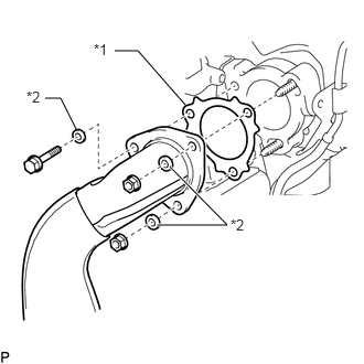
| *1 | Gasket |
| *2 | Spacer |
Install a new gasket.
Temporarily install the front exhaust pipe assembly with a new bolt, 3 spacers and 2 new nuts.
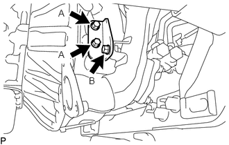
Install the No. 1 exhaust pipe support bracket with the 3 bolts.
- Torque:
- 55 N*m (561 kgf*cm, 41 ft.*lbf)
- NOTICE:
-
Temporarily install the bolt (A), and then tighten the 3 bolts in the order of (B) and (A).
Tighten the 2 nuts and bolt.
- Torque:
- for bolt : 70 N*m (714 kgf*cm, 52 ft.*lbf)
- for nut : 70 N*m (714 kgf*cm, 52 ft.*lbf)
87378C
2.INSTALL EXHAUST PIPE
23811H
3.CONNECT NO. 1 FUEL PIPE
19971G
4.INSTALL VACUUM PIPE
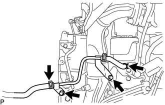
Install the vacuum pipe with the 2 bolts.
- Torque:
- 28.5 N*m (291 kgf*cm, 21 ft.*lbf)
Connect the 2 vacuum hoses.
16028
5.CONNECT NO. 2 TURBO WATER PIPE SUB-ASSEMBLY AND NO. 4 WATER BY-PASS PIPE SUB-ASSEMBLY
6.INSTALL NO. 2 TURBO INSULATOR
7.INSTALL NO. 3 TURBO INSULATOR
18040
8.INSTALL NO. 1 EXHAUST PIPE CONVERTER ASSEMBLY
Install the exhaust pipe support cushion to the No. 1 exhaust pipe support bracket and No. 1 exhaust pipe converter assembly with 4 new nuts.
- Torque:
- 19 N*m (194 kgf*cm, 14 ft.*lbf)
Temporarily install the exhaust pipe support cushion to the No. 1 exhaust pipe converter with 2 new nuts.
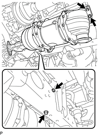
Install the No. 1 exhaust pipe converter assembly with the 2 bolts and 2 new nuts.
- Torque:
- for bolt : 19 N*m (194 kgf*cm, 14 ft.*lbf)
- for nut : 19 N*m (194 kgf*cm, 14 ft.*lbf)
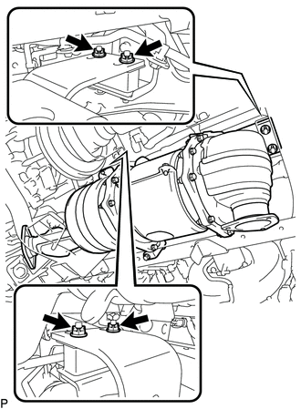
Tighten the 4 nuts.
- Torque:
- 19 N*m (194 kgf*cm, 14 ft.*lbf)
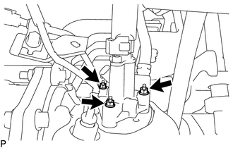
Install a new gasket and connect the urea injector assembly to the No. 1 exhaust pipe converter assembly with the 3 nuts.
- Torque:
- 10 N*m (102 kgf*cm, 7 ft.*lbf)
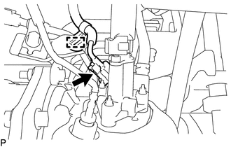
Connect the connector to the urea injector assembly.
Attach the clamp.
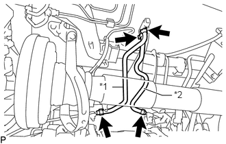
| *1 | No. 1 Air Hose |
| *2 | No. 2 Air Hose |
Connect the No. 2 air hose and secure it with 2 new hose clips.
Connect the No. 1 air hose and secure it with 2 new hose clips.
17402
9.INSTALL FRONT NO. 2 EXHAUST PIPE SUB-ASSEMBLY
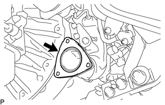
Install a new gasket to the front exhaust pipe assembly.
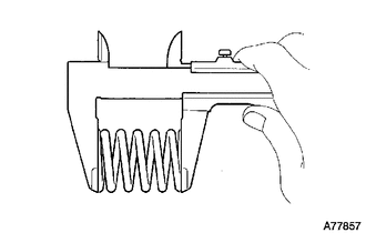
Using a vernier caliper, measure the free length of the compression spring.
- Minimum free length:
38.5 mm (1.52 in.)
If the free length is less than the minimum, replace the compression spring.
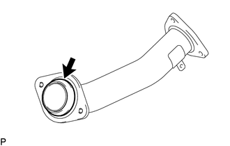
Fully push a new gasket onto the No. 2 front exhaust pipe sub-assembly by hand.
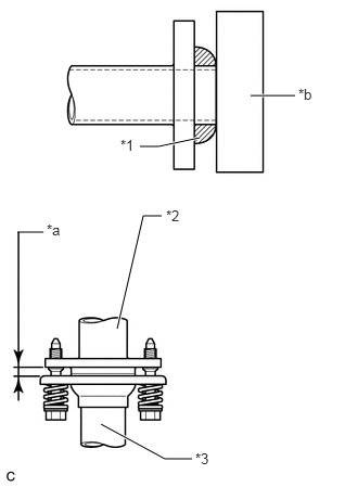
| *1 | Gasket |
| *2 | No. 2 Front Exhaust Pipe Sub-assembly |
| *3 | No. 1 Exhaust Pipe Converter Assembly |
| *a | Gap Between Flanges |
| *b | Wooden Block |
Using a wooden block and hammer, gradually tap the gasket until it is flush with the end face of the No. 2 front exhaust pipe sub-assembly.
- NOTICE:
- ·
Make sure to install the gasket in the correct direction.
·Do not reuse the gasket.
·Do not drop or otherwise damage the gasket.
·Do not damage the sliding portion of the gasket.
·Make sure to push the gasket by hand. Do not push in the gasket as you install the No. 1 front exhaust pipe converter assembly.
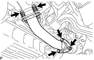
Install the front No. 2 exhaust pipe sub-assembly to the front exhaust pipe assembly with the 3 bolts.
- Torque:
- 43 N*m (438 kgf*cm, 32 ft.*lbf)
Connect the front No. 2 exhaust pipe assembly to the No. 1 exhaust pipe converter assembly with the 2 compression springs and 2 bolts
- Torque:
- 43 N*m (438 kgf*cm, 32 ft.*lbf)
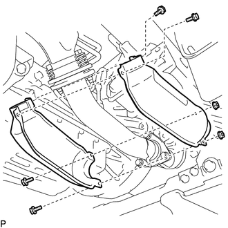
Install the No. 1 exhaust pipe heat insulator sub-assembly and No. 2 exhaust pipe heat insulator sub-assembly to the No. 2 front exhaust pipe sub-assembly with the 4 bolts and 2 nuts.
- Torque:
- 10.8 N*m (110 kgf*cm, 8 ft.*lbf)
18040A
10.INSTALL NO. 2 EXHAUST PIPE CONVERTER ASSEMBLY
Install the exhaust pipe support cushion to the No. 2 exhaust pipe support bracket and No. 2 exhaust pipe converter assembly with 4 new nuts.
- Torque:
- 19 N*m (194 kgf*cm, 14 ft.*lbf)
Temporarily install the exhaust pipe support cushion to the No. 2 exhaust pipe converter assembly with the 2 new nuts.
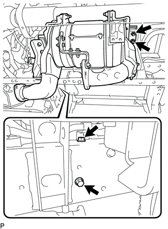
Install the No. 2 exhast pipe converter assembly with the 2 bolts and 2 new nuts.
- Torque:
- for bolt : 22 N*m (224 kgf*cm, 16 ft.*lbf)
- for nut : 19 N*m (194 kgf*cm, 14 ft.*lbf)
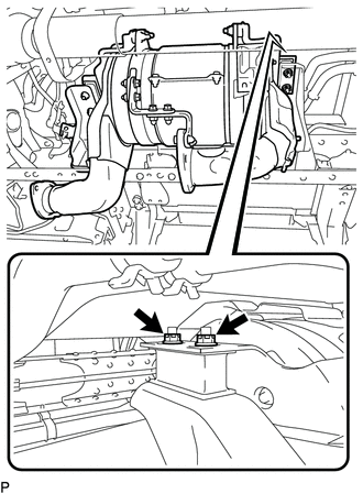
Tighten the 2 nuts.
- Torque:
- 19 N*m (194 kgf*cm, 14 ft.*lbf)
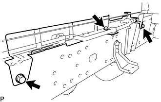
Connect the No. 1 fuel tank heat insulator with the 3 bolts.
- Torque:
- 14 N*m (143 kgf*cm, 10 ft.*lbf)
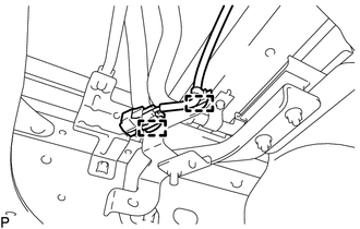
Attach the 2 clamps and connect the wire harness.
17420
11.INSTALL CENTER EXHAUST PIPE ASSEMBLY
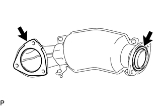
Install the 2 new gaskets to the center exhaust pipe assembly.
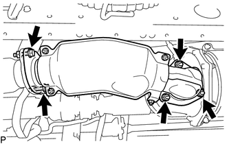
Install the center exhaust pipe assembly with the 2 bolts and 3 nuts.
- Torque:
- 43 N*m (438 kgf*cm, 32 ft.*lbf)
17430
12.INSTALL EXHAUST TAILPIPE ASSEMBLY
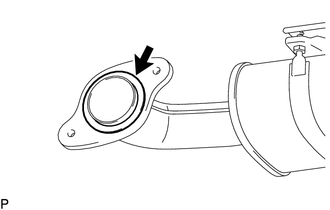
Install a new gasket.
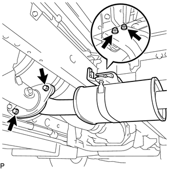
Install the exhaust tailpipe assembly with the 2 new nuts and 2 bolts.
- Torque:
- for bolt : 43 N*m (438 kgf*cm, 32 ft.*lbf)
- for nut : 19 N*m (194 kgf*cm, 14 ft.*lbf)
89425
13.INSTALL EXHAUST GAS TEMPERATURE SENSOR
894A1
14.INSTALL PARTICULATE MATTER SENSOR
15.INSTALL NITROGEN OXIDES SENSOR
16.INSPECT FOR EXHAUST GAS LEAK
If gas is leaking, tighten the areas necessary to stop the leak. Replace damaged parts as necessary.