N04C-WA FUEL COMMON RAIL INSTALLATION
PROCEDURE

 23810A
1.INSTALL COMMON RAIL ASSEMBLY
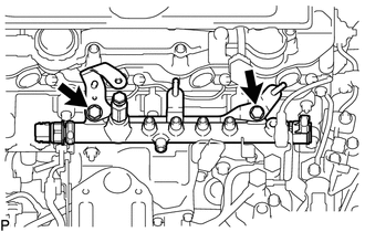
Install the common rail assembly and fuel support with the 2 bolts.
- Torque:
- 55 N*m (561 kgf*cm, 41 ft.*lbf)
Connect the fuel pressure sensor connector.
Connect the fuel pressure discharge valve connector.
2.INSTALL INJECTION PIPE SUB-ASSEMBLY
Temporarily install the injection pipe sub-assembly with the 8 union nuts.
Using a 17 mm union nut wrench, tighten the 8 union nuts.
- Torque:
- Specified tightening torque:
44 N*m (449 kgf*cm, 32 ft.*lbf)
- HINT:
- ·
Calculate the torque wrench reading when changing the fulcrum length of the torque wrench.
·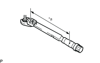 1.667,0.573 1.979,0.729 0.313,0.156 10 false *a
*a Torque Wrench Fulcrum Length
When using a union nut wrench (fulcrum length of 30 mm (1.18 in.)) + torque wrench (fulcrum length of 180 mm (7.09 in.)): 37.7 N*m (384 kgf*cm, 28 ft.*lbf)
23741B
3.INSTALL INJECTION PIPE CLAMP
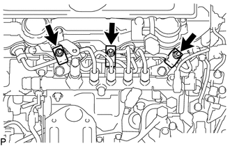
Install the 3 injection pipe clamps with the 3 nuts.
- HINT:
-
Tighten the nut until the clamp edge makes contact with the engine side clamp edge.
23812D
4.INSTALL NO. 2 FUEL PIPE
Using a 17 mm union nut wrench, connect the No. 2 fuel pipe with the 2 union nuts.
- Torque:
- Specified tightening torque:
44 N*m (449 kgf*cm, 32 ft.*lbf)
- HINT:
- ·
Calculate the torque wrench reading when changing the fulcrum length of the torque wrench.
·
1.667,0.573 1.979,0.729 0.313,0.156 10 false *a*a Torque Wrench Fulcrum Length
When using a union nut wrench (fulcrum length of 30 mm (1.18 in.)) + torque wrench (fulcrum length of 180 mm (7.09 in.)): 37.7 N*m (384 kgf*cm, 28 ft.*lbf)
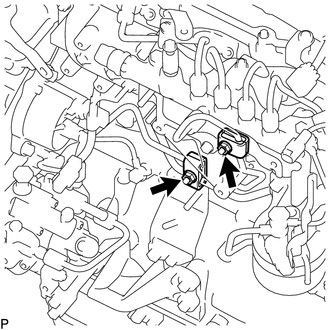
Install the 2 fuel pipe clamps with the 2 nuts.
- HINT:
-
Tighten the nut until the clamp edge makes contact with the engine side clamp edge.
23083
5.INSTALL NO. 3 NOZZLE LEAKAGE PIPE SUB-ASSEMBLY
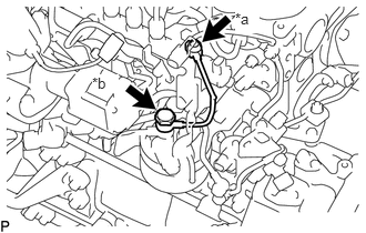
| *a | Union Bolt A |
| *b | Union Bolt B |
Install new 2 gaskets and No. 3 nozzle leakage pipe sub-assembly with the 2 union bolts.
- Torque:
- Union Bolt A : 20.1 N*m (205 kgf*cm, 15 ft.*lbf)
- Union Bolt B : 24.5 N*m (250 kgf*cm, 18 ft.*lbf)
23804D
6.INSTALL NO. 4 FUEL PIPE SUB-ASSEMBLY
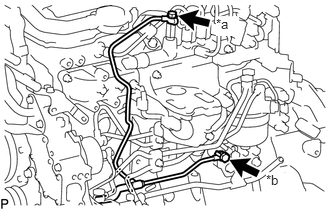
| *a | Union Bolt A |
| *b | Union Bolt B |
Install new 2 gaskets and No. 4 fuel pipe sub-assembly with the 2 union bolts.
- Torque:
- Union Bolt A : 20.1 N*m (205 kgf*cm, 15 ft.*lbf)
- Union Bolt B : 19.6 N*m (200 kgf*cm, 14 ft.*lbf)
Connect the fuel tube.
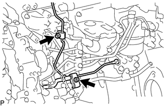
Install the 2 fuel pipe clamps with the 2 nuts.
- HINT:
-
Tighten the nut until the clamp edge makes contact with the engine side clamp edge.
26100
7.INSTALL DIESEL THROTTLE BODY
25608
8.INSTALL EGR COOLER SUB-ASSEMBLY
9.CONNECT CABLE TO NEGATIVE BATTERY TERMINAL
- Torque:
- 5.4 N*m (55 kgf*cm, 48 in.*lbf)
10.BLEED AIR FROM FUEL SYSTEM
11.INSPECT FOR FUEL LEAK
53712C
12.INSTALL FRONT FENDER APRON LH