N04C-VL FUEL FUEL INJECTOR REMOVAL
PROCEDURE

 1.CHECK FOR INJECTOR COMPENSATION CODE
Check that the injector compensation code registered in the injector assembly installed on each cylinder match the ones registered in the ECM.
(Click hereEngine / Hybrid System>N04C-VL (ENGINE CONTROL)>ECD SYSTEM>REGISTRATION)
If they do not match, follow the procedures below to correct the registration details and recheck the symptom.
Correct the registration details by following the procedures in "register injection compensation code".
(Click hereEngine / Hybrid System>N04C-VL (ENGINE CONTROL)>ECD SYSTEM>REGISTRATION)
After correcting the registration details, check if the same symptom occurs as when the vehicle was brought in.
- HINT:
-
If it does not occur, the symptom may be caused by errors in injector compensation code registration.
58410
2.REMOVE ENGINE SERVICE HOLE COVER
58734B
3.REMOVE REAR ENGINE SERVICE COVER WEATHERSTRIP
58521D
4.REMOVE ENGINE SERVICE HOLE COVER MAT
58420
5.REMOVE NO. 2 ENGINE SERVICE HOLE COVER ASSEMBLY
33504F
6.REMOVE SHIFT KNOB
58534A
7.REMOVE TRANSMISSION COVER MAT
58286
8.REMOVE NO. 1 SHIFT AND SELECT LEVER BOOT
33820B
9.DISCONNECT TRANSMISSION CONTROL CABLE ASSEMBLY
33503F
10.REMOVE FLOOR SHIFT SHIFT LEVER SUB-ASSEMBLY
58701A
11.REMOVE FRONT ENGINE SERVICE COVER PANEL SUB-ASSEMBLY
12601B
12.REMOVE NO. 1 ENGINE COVER SUB-ASSEMBLY
11202D
13.REMOVE NO. 2 CYLINDER HEAD COVER SUB-ASSEMBLY
23741B
14.REMOVE INJECTION PIPE CLAMP
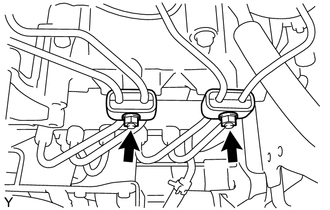
Remove the 2 nuts and the 2 injection pipe clamps.
23670
15.REMOVE INJECTOR ASSEMBLY
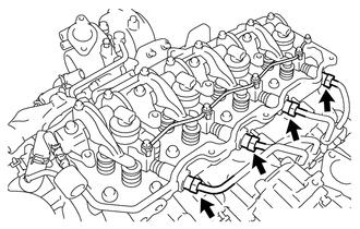
Using a union nut wrench (17 mm), loosen the 4 injection pipe union nuts and disconnect the No. 1, No. 2, No. 3 and No. 4 injection pipes.
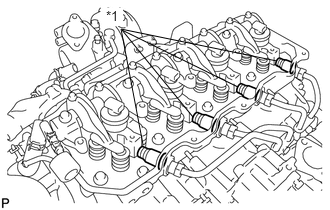
Using a small screwdriver, remove the 4 holder seals.
| *1 | Holder Seal |
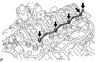
Remove the union bolt, 4 hollow screws, 5 gaskets and nozzle leakage pipe.
- NOTICE:
- ·
After removing the nozzle leakage pipe, put it in a plastic bag to prevent foreign matter from contaminating its injector.
·Be sure to prevent foreign matter or water from entering the lines.
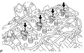
Remove the 4 clamp bolts and 4 nozzle holder clamps.
- NOTICE:
-
Arrange the holder clamps and bolts in the correct order.
Remove the 4 injector assemblies.
- NOTICE:
-
Arrange the injector assemblies in the correct order.
Remove the No. 2 cylinder head cover gasket from each injector assembly.
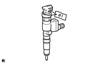
Engage tags to identify the cylinder (#1 to #4) to the injector assemblies so that each injector assembly can be inserted into the correct cylinder during installation.
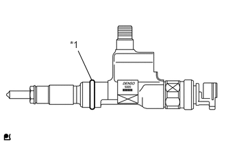
Remove the O-ring from each injector assembly.
| *1 | O-ring |
Remove the 4 injection nozzle seats from the cylinder head.