N04C-VL ENGINE MECHANICAL ENGINE ASSEMBLY REMOVAL
PROCEDURE

 16400
1.REMOVE RADIATOR ASSEMBLY
33110
2.REMOVE MANUAL TRANSMISSION ASSEMBLY
31250
3.REMOVE CLUTCH DISC ASSEMBLY
(Click hereDrivetrain>CLUTCH>CLUTCH UNIT (for M551)>REMOVAL)
17201
4.REMOVE TURBOCHARGER SUB-ASSEMBLY
16577C
5.REMOVE RADIATOR PIPE
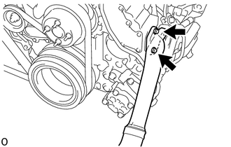
Remove the 2 bolts and remove the radiator pipe.
Remove the gasket.
88320
6.SEPARATE COOLER COMPRESSOR ASSEMBLY (w/ Air Conditioning System)
Disconnect the connector.
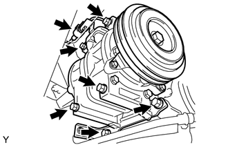
Remove the 6 bolts and separate the cooler compressor assembly.
27020
7.REMOVE GENERATOR ASSEMBLY
44360
8.SEPARATE VANE PUMP OIL RESERVOIR ASSEMBLY
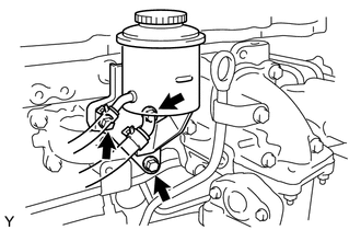
Remove the 3 bolts and vane pump oil reservoir assembly.
53712C
9.REMOVE FRONT FENDER APRON LH
44310
10.SEPARATE VANE PUMP ASSEMBLY
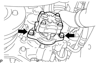
Remove the 2 bolts and separate the vane pump assembly.
Remove the O-ring.
17342P
11.REMOVE NO. 2 AIR HOSE
44774
12.DISCONNECT UNION TO CONNECTOR TUBE HOSE
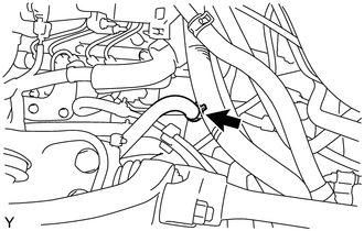
Disconnect the union to connector tube hose.
22100A
13.DISCONNECT INJECTION PUMP TO FUEL FILTER FUEL HOSE OR PIPE
14.DISCONNECT NO. 1 FUEL HOSE RETURN TUBE
28100
15.REMOVE STARTER ASSEMBLY
87246B
16.DISCONNECT OUTLET HEATER WATER HOSE B
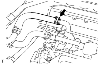
Slide the clamp and disconnect the outlet heater water hose B.
87245B
17.DISCONNECT INLET HEATER WATER HOSE B
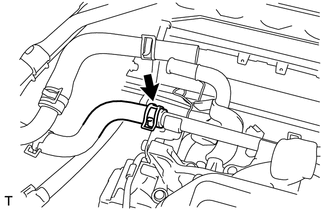
Slide the clamp and disconnect the inlet heater water hose B.
45470
18.SEPARATE TIE ROD ASSEMBLY LH
Remove the cotter pin.
Remove the nut.
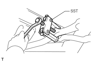
Using SST, separate the tie rod assembly LH from the steering relay rod assembly.
- SST
- 09628-62011
45450
19.SEPARATE STEERING RELAY ROD ASSEMBLY
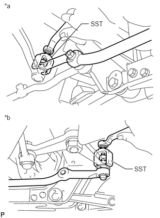
| *a | for Idler Arm Bracket Assembly Side |
| *b | for Center Arm Bracket Assembly Side |
Remove the 2 cotter pins.
Remove the 2 nuts.
Using SST, separate the steering relay rod assembly from the center arm bracket assembly and idler arm bracket assembly.
- SST
- 09611-20015
51202D
20.REMOVE FRONT LOWER SUSPENSION CROSSMEMBER SUB-ASSEMBLY
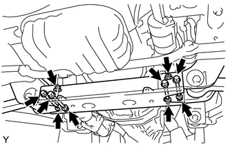
Remove the 6 bolts, 4 nuts, 4 washers and front lower suspension crossmember sub-assembly.
- HINT:
-
While fixing the nut in place, loosen and remove the through bolt.
82121
21.SEPARATE ENGINE WIRE
Separate all engine wires from the engine.
22.REMOVE ENGINE ASSEMBLY
Support the engine using an engine lifter.
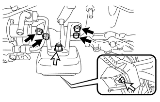
Remove the 2 nuts and washer.

|
Bolt |

|
Nut |
Remove the 4 bolts and front No. 1 engine mounting bracket LH.
Remove the engine mounting stabilizer and engine mounting insulator.
Remove the 2 nuts and washer.
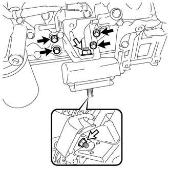
Remove the 4 bolts and front No. 1 engine mounting bracket RH.
|
|
Bolt |
|
|
Nut |
Remove the engine mounting stabilizer and engine mounting insulator.
Remove the engine assembly.
12601B
23.REMOVE NO. 1 ENGINE COVER SUB-ASSEMBLY
Remove the 2 bolts, 2 cylinder head cover stays and No. 1 engine cover sub-assembly.
11202D
24.REMOVE NO. 2 CYLINDER HEAD COVER SUB-ASSEMBLY
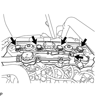
Remove the bolt and disconnect the 4 connectors and remove the wire harness.
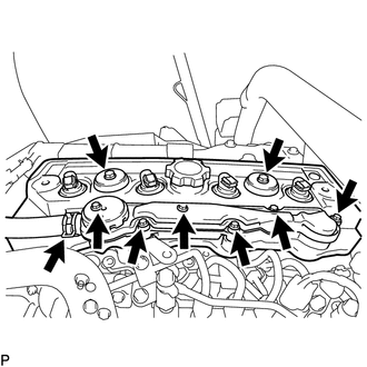
Disconnect the PCV hose and, remove the 6 bolts and oil separator assembly.
Remove the 2 bolts, 2 cylinder head cover stay and 2 cylinder head cushion.
Remove the No. 2 cylinder head cover sub-assembly and cylinder head cover gasket.
Remove the 4 No. 2 cylinder head cover gaskets.
25625
25.REMOVE EGR VALVE BRACKET
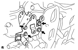
Remove the 4 bolts and EGR valve bracket.
15301
26.REMOVE OIL DIPSTICK GUIDE
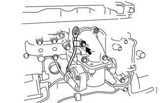
Remove the bolt and oil dipstick guide.
Remove the O-ring.
27.REMOVE INTAKE PIPE WITH VENTURI ASSEMBLY
17138A
28.REMOVE INTAKE PIPE STAY
Remove the 4 bolts and intake pipe.
23741B
29.REMOVE INJECTION PIPE CLAMP
23670
30.REMOVE INJECTOR ASSEMBLY
17111
31.REMOVE INTAKE MANIFOLD
17141
32.REMOVE EXHAUST MANIFOLD
83530
33.REMOVE ENGINE OIL PRESSURE SWITCH ASSEMBLY
15710
34.REMOVE OIL COOLER ASSEMBLY
89422
35.REMOVE ENGINE COOLANT TEMPERATURE SENSOR
36.REMOVE CRANKSHAFT POSITION SENSOR
37.REMOVE CAMSHAFT POSITION SENSOR
16630G
38.REMOVE IDLER PULLEY ASSEMBLY
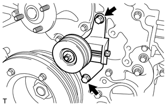
Remove the 2 bolts and idler pulley assembly.
88444
39.REMOVE IDLE PULLEY ASSEMBLY WITH BRACKET (w/ Air Conditioning System)
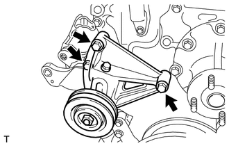
Remove the 3 bolts and idle pulley assembly with bracket.
88431
40.REMOVE NO. 1 COMPRESSOR MOUNTING BRACKET (w/ Air Conditioning System)
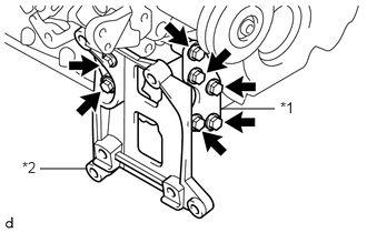
Remove the 7 bolts, compressor mounting bracket set and No. 1 compressor mounting bracket.
| *1 | Compressor Mounting Bracket Set |
| *2 | No. 1 Compressor Mounting Bracket |
16331
41.REMOVE WATER OUTLET
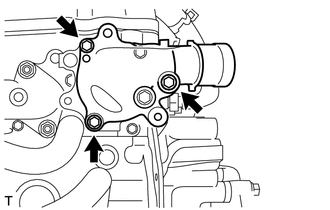
Remove the 3 bolts and water outlet.
16331A
42.REMOVE THERMOSTAT
16333
43.REMOVE WATER OUTLET HOUSING
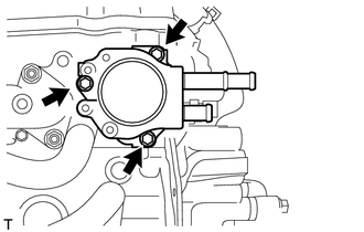
Remove the 3 bolts, water outlet housing and gasket.
87208L
44.REMOVE WATER PIPE SUB-ASSEMBLY
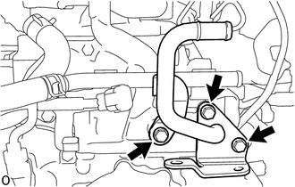
Remove the 3 bolts, water pipe sub-assembly and O-ring.
16206B
45.REMOVE NO. 3 WATER BY-PASS PIPE SUB-ASSEMBLY
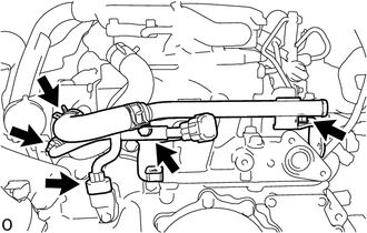
Disconnect the 2 connectors.
Slide the clamp and disconnect the water hose.
Remove the 2 bolts and No. 3 water by-pass pipe sub-assembly.
16206
46.REMOVE WATER BY-PASS PIPE SUB-ASSEMBLY
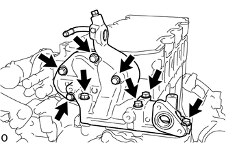
Remove the 8 bolts and water by-pass pipe sub-assembly.
Remove the 2 gaskets and 3 O-rings.
16100
47.REMOVE ENGINE WATER PUMP ASSEMBLY
23811
48.REMOVE FUEL FILTER TO INJECTION PUMP FUEL PIPE
23803H
49.REMOVE FUEL RETURN PIPE SUB-ASSEMBLY
19971E
50.REMOVE VACUUM PIPE
Remove the bolt and nut and remove the 2 pipe clamps.
29601B
51.REMOVE VACUUM PUMP OIL PIPE SUB-ASSEMBLY
29300
52.REMOVE VACUUM PUMP ASSEMBLY
12204
53.REMOVE VENTILATION VALVE SUB-ASSEMBLY
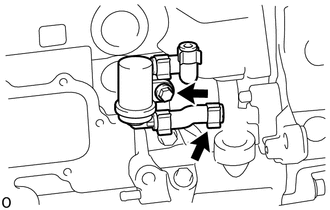
Slide the clamp and disconnect the hose.
Remove the bolt and ventilation valve sub-assembly.
16206A
54.REMOVE NO. 2 WATER BY-PASS PIPE SUB-ASSEMBLY
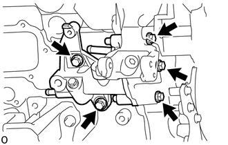
Remove the 5 bolts and No. 2 water by-pass pipe sub-assembly.
Remove the 3 O-rings.
55.REMOVE NO. 3 NOZZLE LEAKAGE PIPE SUB-ASSEMBLY
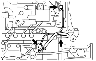
Loosen the hose clamp, 2 union bolts, 2 gaskets and the No. 3 nozzle leakage pipe sub-assembly.
23810A
56.REMOVE COMMON RAIL ASSEMBLY
23849G
57.REMOVE FUEL PIPE SUPPORT
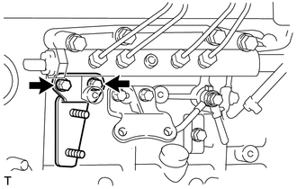
Remove the 2 bolts and fuel pipe support.
82702E
58.REMOVE WIRING HARNESS BRACKET SUB-ASSEMBLY
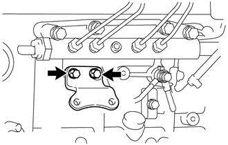
Remove the 2 bolts and wiring harness bracket sub-assembly.
59.REMOVE COMMON RAIL ASSEMBLY FUEL PIPE SUPPORT
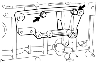
Remove the 2 bolts and common rail assembly fuel pipe support.
22100
60.REMOVE INJECTION OR SUPPLY PUMP ASSEMBLY