N04C-UH FUEL FUEL SUPPLY PUMP REMOVAL
PROCEDURE

 58410
1.REMOVE ENGINE SERVICE HOLE COVER
58734B
2.REMOVE ENGINE SERVICE COVER WEATHERSTRIP REAR
58521D
3.REMOVE ENGINE SERVICE HOLE COVER MAT
58420
4.REMOVE NO. 2 ENGINE SERVICE HOLE COVER ASSEMBLY
58534A
5.REMOVE TRANSMISSION COVER MAT
33531B
6.REMOVE SHIFT AND SELECT LEVER SHAFT DUST BOOT
33820B
7.DISCONNECT TRANSMISSION CONTROL CABLE ASSEMBLY
33504F
8.REMOVE SHIFT LEVER SUB-ASSEMBLY
58701A
9.REMOVE FRONT ENGINE SERVICE COVER PANEL SUB-ASSEMBLY
51459
10.REMOVE ENGINE SIDE COVER STAY (for TCAP Made)
51441D
11.REMOVE NO. 1 ENGINE UNDER COVER (for Plastic Type)
51441D
12.REMOVE NO. 1 ENGINE UNDER COVER (for Metal Type)
53712C
13.REMOVE FRONT FENDER APRON LH
14.DRAIN ENGINE COOLANT
15.SET NO. 1 CYLINDER TO TDC / COMPRESSION
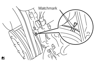
Turn the crankshaft pulley clockwise, and align the matchmarks as shown in the illustration.
If not, turn the crankshaft 1 revolution (360°) and align the matchmarks as above.
16206C
16.SEPARATE WATER BY-PASS PIPE SUB-ASSEMBLY
17113
17.REMOVE INTAKE PIPE
17271
18.REMOVE NO. 1 TURBO INSULATOR
25608
19.REMOVE EGR COOLER SUB-ASSEMBLY
20.SEPARATE WIRE HARNESS AND CONNECTORS
25625B
21.REMOVE EGR VALVE BRACKET
44360
22.SEPARATE VANE PUMP OIL RESERVOIR ASSEMBLY
17342P
23.REMOVE NO. 2 AIR HOSE
15301
24.REMOVE OIL DIPSTICK GUIDE
17113
25.REMOVE INTAKE PIPE WITH VENTURI ASSEMBLY
16206
26.REMOVE WATER BY-PASS PIPE SUB-ASSEMBLY
27.REMOVE NO. 2 INTAKE PIPE WITH EGR VALVE
22100A
28.DISCONNECT INJECTION PUMP TO FUEL FILTER FUEL HOSE OR PIPE
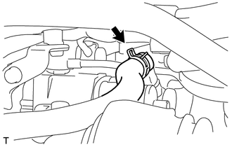
Move the clamp and disconnect the hose.
23271H
29.DISCONNECT NO. 1 FUEL HOSE RETURN TUBE
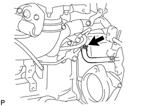
Move the clamp and disconnect the hose.
23807
30.REMOVE FUEL DELIVERY PIPE SUB-ASSEMBLY
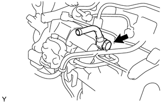
Remove the union bolt, the 2 gaskets and the fuel delivery pipe sub-assembly.
31.REMOVE NO. 2 HARNESS BRACKET
32.REMOVE NO. 1 HARNESS BRACKET
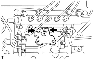
Remove the 2 bolts and the No. 1 harness bracket.
23801L
33.REMOVE FUEL FILTER TO INJECTION PUMP FUEL PIPE SUB-ASSEMBLY
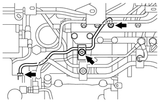
Remove the nut and the fuel pipe clamp.
Using a union nut wrench (17 mm), loosen the 2 union nuts.
Remove the fuel filter to injection pump fuel pipe.
23803H
34.REMOVE FUEL RETURN PIPE SUB-ASSEMBLY
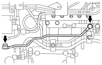
Remove the 2 union bolts and 3 gaskets.
Remove the fuel return pipe sub-assembly.
11301K
35.REMOVE CRANKSHAFT POSITION SENSOR
22100
36.REMOVE INJECTION OR SUPPLY PUMP ASSEMBLY
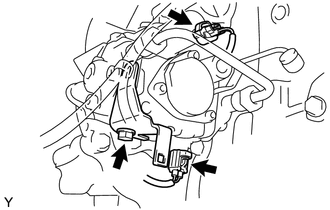
Disconnect the 2 connectors.
Remove the bolt and the holder clip.
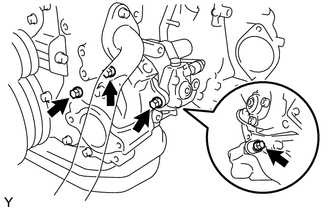
Remove the 4 bolts and the injection or supply pump assembly.
Remove the O-ring from the timer cover.
13613
37.REMOVE INJECTION PUMP DRIVE GEAR
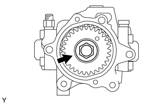
Clamp the injection or supply pump assembly in a soft jaw vise.
Remove the nut, the injection pump drive gear and the crankshaft angle sensor plate.
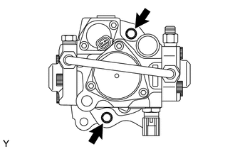
Remove the 2 bolts and the timer cover.
Remove the O-ring from the timer cover.