2GR-FE ENGINE CONTROL SFI SYSTEM P1585 Acceleration Sensor Circuit P1586 Acceleration Sensor Malfunction
DESCRIPTION
The ECM detects the yaw rate based on a signal sent from the yaw rate sensor and uses this information for neutral control. If the ECM detects a malfunction based on a fault signal sent from the skid control ECU, the ECM prohibits neutral control as a fail-safe function.
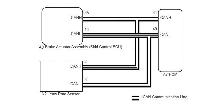
The skid control ECU supplies power to the yaw rate sensor and records the sensor data. The data is shared by the ECM via CAN. Zero point calibration and operation is performed by each ECU.
- HINT:
-
If a CAN communication DTC is output, perform troubleshooting for that DTC first.
| DTC Code | DTC Detection Condition
1.
Diagnosis Condition 2.
Malfunction Status 3.
Malfunction Time 4.
Other |
Trouble Area |
|---|---|---|
| P1585 | 1.
Engine switch on (IG). 2.
The output value of the yaw rate sensor remains at -1.5 G or less, or 1.5 G or more for at least 1.2 seconds. 3.
0.5 seconds 4.
1 trip detection logic |
·
Yaw rate sensor circuit ·
Yaw rate sensor ·
Brake actuator assembly (Skid control ECU) ·
CAN communication system ·
ECM |
1.
Engine switch on (IG). 2.
The power source voltage to the yaw rate sensor remains at 4.4 V or less, or 5.6 V or higher for at least 1.2 seconds. 3.
0.5 seconds 4.
1 trip detection logic |
||
1.
Engine switch on (IG). 2.
No signal from the yaw rate sensor is detected 7 times or more. 3.
0.5 seconds 4.
1 trip detection logic |
||
1.
Engine switch on (IG). 2.
With the vehicle stopped, the difference between GL1 and GL2 does not become less than 0.4 G within 60 seconds after exceeding 0.6 G. 3.
0.5 seconds 4.
1 trip detection logic |
||
1.
Engine switch on (IG). 2.
A yaw rate sensor power source voltage malfunction signal is received for at least 10 seconds with the vehicle speed at 3 km/h (1.8 mph) or more. 3.
0.5 seconds 4.
1 trip detection logic |
||
| P1586 | 1.
Engine switch on (IG) 2.
With the vehicle speed 30 km/h (18 mph) or more, the difference between the longitudinal acceleration calculated based on the yaw rate sensor value and the longitudinal acceleration calculated based on the vehicle speed exceeds 0.35 G for 60 seconds or more. 3.
0.5 seconds 4.
1 trip detection logic |
|
1.
Engine switch on (IG) 2.
No change detected in the yaw rate sensor signal 16 times or more while the vehicle speed decreases from 30 km/h (18 mph) to 0 km/h (0 mph). 3.
0.5 seconds 4.
1 trip detection logic |
WIRING DIAGRAM
PROCEDURE
Connect the intelligent tester to the DLC3.
Turn the engine switch to on (IG).
Turn the tester on.
Enter the following menus: Chassis / ABS/VSC/TRC / DTC.
Read the DTCs.
Check for DTCs of the CAN communication system (See page Power Source / Network>CAN COMMUNICATION>CAN COMMUNICATION SYSTEM>HOW TO PROCEED WITH TROUBLESHOOTING).
| Result | Proceed to |
|---|---|
| DTC is not output | A |
| DTC is output (vehicle stability control system) | B |
| DTC is output (CAN communication system) | C |
- HINT:
- ·
If the VSC system stores a yaw rate sensor system DTC, the yaw rate sensor or skid control ECU may be malfunctioning.
·The skid control ECU stores DTCs to indicate a yaw rate sensor power malfunction, stuck malfunction or abnormal output value.
·Check carefully when any DTCs indicating an ECU power malfunction or ECU internal malfunction are output.
·If DTC P1589 (abnormal acceleration sensor learning value) is output with other DTCs, perform zero point calibration of the yaw rate sensor first (deceleration sensor zero point calibration).
A
B
C
(See pagePower Source / Network>CAN COMMUNICATION>CAN COMMUNICATION SYSTEM>DIAGNOSTIC TROUBLE CODE CHART)
Perform zero point calibration of the yaw rate sensor (deceleration sensor zero point calibration) (See page Drivetrain>U660E (AUTOMATIC TRANSMISSION / TRANSAXLE)>AUTOMATIC TRANSAXLE SYSTEM>INITIALIZATION).
NEXT
Connect the intelligent tester to the DLC3.
Turn the engine switch to on (IG).
Turn the tester on.
Clear the DTCs (See page Engine / Hybrid System>2GR-FE ENGINE CONTROL>SFI SYSTEM>DTC CHECK / CLEAR).
Drive the vehicle.
Enter the following menus: Powertrain / Engine / DTC.
Read the DTCs.
| Result | Proceed to |
|---|---|
| DTC is not output | A |
| DTC P1585 or P1586 is output | B |
A
B