2GR-FE EMISSION CONTROL AIR FUEL RATIO SENSOR INSTALLATION
PROCEDURE

 89467C
1.INSTALL AIR FUEL RATIO SENSOR NO.2 (for Bank 2 Sensor 1)
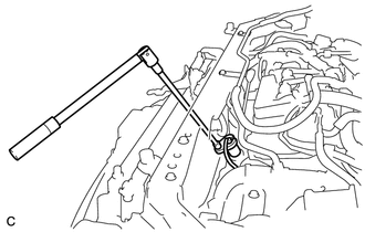
Using SST, install the sensor to the exhaust manifold LH.
- SST
- 09224-00010
- Torque:
- 40 N*m (408 kgf*cm, 30 ft.*lbf)
for use with SST
- 44 N*m (449 kgf*cm, 32 ft.*lbf)
for use without SST
- HINT:
- ·
Use a torque wrench with a fulcrum length of 30 cm (11.81 in.).
·Make sure that SST and wrench are connected in a straight line.
Connect the sensor connector.
89257
2.INSTALL COOLING FAN ECU
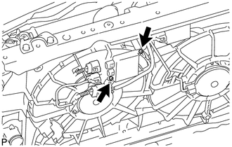
Install the cooling fan ECU with the 2 screws.
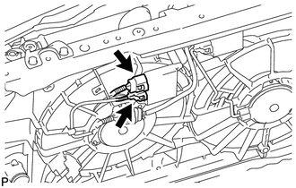
Connect the cooling fan ECU connector.
86520
3.INSTALL LOW PITCHED HORN
53101
4.INSTALL RADIATOR GRILLE
Install the 3clips and screw.
53292A
5.INSTALL UPPER RADIATOR SUPPORT SEAL
89467B
6.INSTALL AIR FUEL RATIO SENSOR (for Bank 1 Sensor 1)
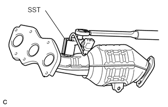
Using SST, install the sensor to the exhaust manifold RH.
- SST
- 09224-00010
- Torque:
- 40 N*m (408 kgf*cm, 30 ft.*lbf)
for use with SST
- 44 N*m (449 kgf*cm, 32 ft.*lbf)
for use without SST
- HINT:
- ·
Use a torque wrench with a fulcrum length of 30 cm (11.81 in.).
·Make sure that SST and wrench are connected in a straight line.
Connect the sensor connector.
17420
7.INSTALL EXHAUST MANIFOLD RH
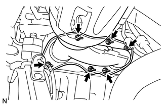
Install exhaust manifold RH with a new gasket and 6 bolts.
- Torque:
- 21 N*m (214 kgf*cm, 15 ft.*lbf)
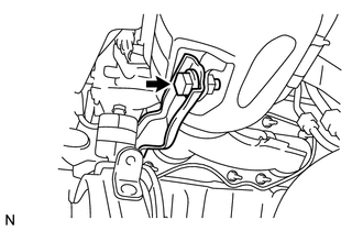
Install the exhaust manifold stay with the bolt.
- Torque:
- 34 N*m (347 kgf*cm, 25 ft.*lbf)
Connect the air fuel ratio sensor (for Bank 1 Sensor 1) connector.
89465
8.INSTALL CENTER EXHAUST PIPE ASSEMBLY
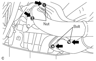
Install 2 new gaskets to the center exhaust pipe assembly.
Install the center exhaust pipe assembly with the 2 nuts and 2 bolts.
- Torque:
- Bolt : 43 N*m (440 kgf*cm, 32 ft.*lbf)
- Nut : 55 N*m (561 kgf*cm, 41 ft.*lbf)
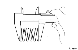
Check compression springs.
Check the compression springs using a vernier caliper.
- Specified length:
41.7 mm (1.6417 in.)
- HINT:
-
If the result is not as specified, replace the compression spring.
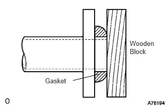
Install the gasket.
Install a new gasket by hand onto the center exhaust pipe assembly.
Using a plastic hammer and wooden block, tap in the new gasket until its surface is flush with the exhaust front pipe.
- NOTICE:
- ·
Be careful with the installation direction of the gasket.
·Do not damage the gasket.
·Do not reuse the gasket.
·To ensure a proper seal, do not use the exhaust pipe to force the gasket on to the front exhaust pipe.
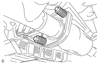
Install the center exhaust pipe assembly with the 2 bolts.
- Torque:
- 43 N*m (440 kgf*cm, 32 ft.*lbf)
Connect the heated oxygen sensor (for Bank 1 sensor 2) connector.
28800
9.CONNECT CABLE TO NEGATIVE BATTERY TERMINAL
- NOTICE:
-
When disconnecting the cable, some systems need to be initialized after the cable is reconnected (See page General>INTRODUCTION>REPAIR INSTRUCTION>INITIALIZATION).
10.INSPECT FOR EXHAUST GAS LEAK