2GR-FE EXHAUST EXHAUST PIPE INSTALLATION
PROCEDURE

 89465A
1.INSTALL HEATED OXYGEN SENSOR (for Bank 2 Sensor 2)
17410
2.INSTALL FRONT EXHAUST PIPE ASSEMBLY
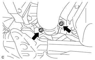
Install a new gasket to the front exhaust pipe assembly.
Install the front exhaust pipe assembly with the 2 nuts.
- Torque:
- 55 N*m (561 kgf*cm, 41 ft.*lbf)
Connect the heated oxygen sensor (for bank 2 sensor 2) connector.
17584B
3.INSTALL NO. 1 EXHAUST PIPE SUPPORT BRACKET
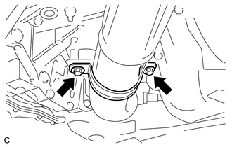
Install the No. 1 exhaust pipe support bracket with the 2 bolts.
- Torque:
- 21 N*m (214 kgf*cm, 15 ft.*lbf)
17420
4.INSTALL CENTER EXHAUST PIPE ASSEMBLY
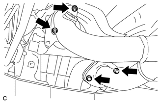
Install 2 new gaskets to the center exhaust pipe assembly.
Install the center exhaust pipe assembly with the 2 nuts and 2 bolts.
- Torque:
- Bolt : 43 N*m (440 kgf*cm, 32 ft.*lbf)
- Nut : 55 N*m (561 kgf*cm, 41 ft.*lbf)
17403A
5.INSTALL NO. 2 EXHAUST PIPE SUB-ASSEMBLY
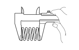
Using a vernier caliper, measure the free length of the compression spring.
- Minimum length:
41.5 mm (1.634 in.)
If the length is less than the minimum, replace the compression spring.
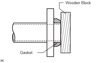
Using a plastic-faced hammer and wooden block, tap in a new gasket until its surface is flush with the center exhaust pipe assembly.
- NOTICE:
- ·
Tap in the gasket in the correct direction.
·Do not reuse the removed gasket.
·Do not push in the gasket while installing the No. 2 exhaust pipe sub-assembly.
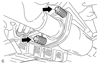
Install the No. 2 exhaust pipe sub-assembly with the 2 compression springs and 2 bolts.
- Torque:
- 43 N*m (440 kgf*cm, 32 ft.*lbf)
17430
6.INSTALL TAIL EXHAUST PIPE ASSEMBLY
Using a vernier caliper, measure the free length of the compression spring.
- Minimum length:
38.5 mm (1.516 in.)
If the length is less than the minimum, replace the compression spring.
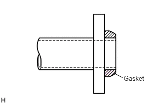
Install a new gasket by hand so that its surface is flush with the No. 2 exhaust pipe sub-assembly.
- NOTICE:
- ·
Make sure the gasket is facing the correct direction.
·Do not reuse the removed gasket.
·Do not push in the gasket while installing the tail exhaust pipe assembly.
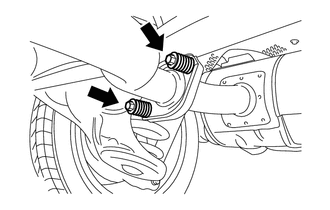
Install the tail exhaust pipe assembly with the 2 compression springs and 2 bolts.
- Torque:
- 43 N*m (440 kgf*cm, 32 ft.*lbf)
89465
7.INSTALL HEATED OXYGEN SENSOR (for Bank 1 Sensor 2)
28800
8.CONNECT CABLE TO NEGATIVE BATTERY TERMINAL
- HINT:
-
When disconnecting the cable, some systems need to be initialized after the cable is reconnected (See Page General>INTRODUCTION>REPAIR INSTRUCTION>INITIALIZATION).
9.INSPECT FOR EXHAUST GAS LEAK
If exhaust gas is leaking, repair the leak. Replace damaged or worn parts as necessary.