POWER STEERING STEERING GEAR REMOVAL
PROCEDURE

 1.POSITION FRONT WHEELS FACING STRAIGHT AHEAD
28800
2.DISCONNECT CABLE FROM NEGATIVE BATTERY TERMINAL
- CAUTION:
-
Wait at least 90 seconds after disconnecting the cable from the negative (-) battery terminal to prevent airbag and seat belt pretensioner activation.
45259A
3.REMOVE COLUMN HOLE COVER SILENCER SHEET
45260
4.DISCONNECT NO. 2 STEERING INTERMEDIATE SHAFT ASSEMBLY
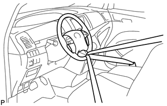
Use a seat belt to fix the steering wheel in place to avoid breakage of the spiral cable.
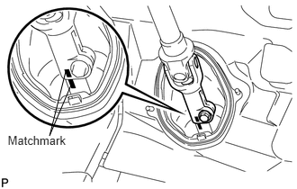
Place matchmarks on the sliding yoke of the steering intermediate shaft.
Remove the bolt and disconnect the sliding yoke.
45025D
5.DISCONNECT NO. 1 STEERING COLUMN HOLE COVER SUB-ASSEMBLY
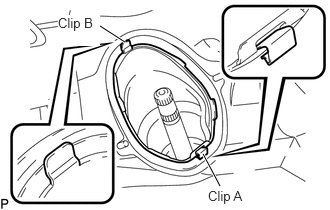
Remove clip A, detach clip B from the body and disconnect the No. 1 steering column hole cover.
- NOTICE:
-
Do not damage clips A and B.
6.REMOVE FRONT WHEEL
51441
7.REMOVE NO. 1 ENGINE UNDER COVER
51442
8.REMOVE NO. 2 ENGINE UNDER COVER
53702
9.REMOVE FRONT FENDER APRON LH
53701
10.REMOVE FRONT FENDER APRON RH
- HINT:
-
Use the same procedure for the RH side as for the LH side.
51218A
11.REMOVE FRONT SUSPENSION MEMBER REINFORCEMENT LH
51217A
12.REMOVE FRONT SUSPENSION MEMBER REINFORCEMENT RH
- HINT:
-
Use the same procedure for the RH side as for the LH side.
48810
13.REMOVE FRONT STABILIZER LINK ASSEMBLY LH
48820B
14.REMOVE FRONT STABILIZER LINK ASSEMBLY RH
- HINT:
-
Use the same procedure for the RH side as for the LH side.
45407
15.DISCONNECT TIE ROD END SUB-ASSEMBLY LH
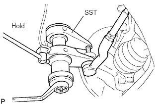
Using SST, disconnect the tie rod end from the steering knuckle.
- SST
- 09628-00011
- NOTICE:
-
Do not damage the tie rod end dust cover.
45046
16.DISCONNECT TIE ROD END SUB-ASSEMBLY RH
- HINT:
-
Use the same procedure for the RH side as for the LH side.
17.REMOVE FRONT AXLE ASSEMBLY LH
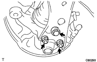
Remove the bolt and 2 nuts.
Push down the front suspension lower arm and remove the front axle from the front lower ball joint LH.
18.REMOVE FRONT AXLE ASSEMBLY RH
- HINT:
-
Use the same procedure for the RH side as for the LH side.
51201
19.REMOVE FRONT SUSPENSION CROSSMEMBER SUB-ASSEMBLY (for 2AZ-FE)
51201
20.REMOVE FRONT SUSPENSION CROSSMEMBER SUB-ASSEMBLY (for 2GR-FE)
45221
21.REMOVE STEERING INTERMEDIATE SHAFT
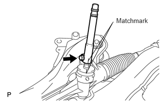
Place matchmarks on the intermediate shaft of the steering gear.
Remove the bolt and disconnect the steering intermediate shaft from the steering gear.
45510
22.REMOVE STEERING GEAR ASSEMBLY
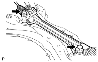
Remove the 2 bolts, 2 nuts and steering gear from the suspension crossmember.
- NOTICE:
-
Keep the nut from rotating while turning the bolt.