2GR-FE ENGINE MECHANICAL ENGINE ASSEMBLY REMOVAL
PROCEDURE

 1.RECOVER REFRIGERANT FROM REFRIGERATION SYSTEM
2.DISCHARGE FUEL SYSTEM PRESSURE
3.PLACE FRONT WHEELS FACING STRAIGHT AHEAD
28800J
4.DISCONNECT CABLE FROM NEGATIVE BATTERY TERMINAL
- CAUTION:
-
Wait at least 90 seconds after disconnecting the cable from the negative (-) battery terminal to prevent airbag and seat belt pretensioner activation.
5.REMOVE FRONT WHEEL
51441
6.REMOVE NO. 1 ENGINE UNDER COVER
51442
7.REMOVE NO. 2 ENGINE UNDER COVER
51441D
8.REMOVE ENGINE UNDER COVER
53701
9.REMOVE FRONT FENDER APRON RH
53702
10.REMOVE FRONT FENDER APRON LH
11.DRAIN ENGINE OIL
12.DRAIN ENGINE COOLANT
13.DRAIN AUTOMATIC TRANSAXLE FLUID
53292A
14.REMOVE UPPER RADIATOR SUPPORT SEAL
11209
15.REMOVE V-BANK COVER ASSEMBLY
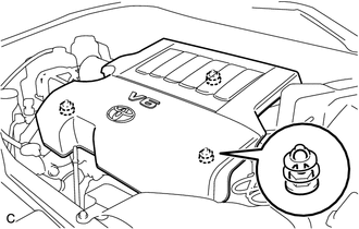
Hold the front of the V-bank cover and raise it to disengage the 2 clips on the front of the cover. Continue to raise the cover to disengage the clip on the rear of the cover and remove the cover.
- NOTICE:
-
Attempting to disengage both front and rear clips at the same time may cause the cover to break.
53301
16.REMOVE HOOD SUB-ASSEMBLY
Remove the 4 bolts and hood.
16470
17.REMOVE RADIATOR RESERVOIR ASSEMBLY
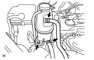
Disconnect the No. 1 and No. 2 water by-pass hose.
Remove the bolt and reservoir.
16611
18.REMOVE RADIATOR RESERVOIR BRACKET
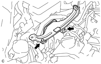
Remove the 2 bolts and radiator reservoir bracket.
19.REMOVE FRONT WIPER ARM
55781F
20.REMOVE COWL TOP VENTILATOR LOUVER
21.REMOVE BRAKE MASTER CYLINDER RESERVOIR SUB-ASSEMBLY
22.REMOVE FRONT COWL TOP OUTSIDE PANEL WITH WINDSHIELD WIPER MOTOR AND LINK
28800
23.REMOVE BATTERY
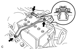
Disconnect the 2 wire clamps.
Loosen the nut, and remove the bolt with the battery clamp.
Remove the battery and battery tray.
17705
24.REMOVE AIR CLEANER CAP SUB-ASSEMBLY
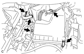
Disconnect the mass air flow meter connector and clamp.
Disconnect the ventilation hose.
Remove the hose band and air cleaner cap.
Remove the air cleaner filter element.
17700
25.REMOVE AIR CLEANER CASE SUB-ASSEMBLY
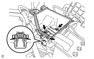
Disconnect the wire clamp.
Remove the 3 bolts and air cleaner case.
17751
26.REMOVE NO. 1 AIR CLEANER INLET
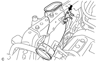
Disconnect the clip and remove the No. 1 air cleaner inlet.
17752
27.REMOVE NO. 2 AIR CLEANER INLET
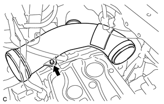
Remove the bolt and No. 2 air cleaner inlet.
74411
28.REMOVE BATTERY CARRIER
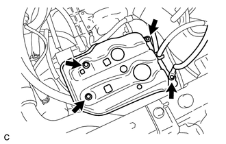
Remove the 4 bolts and battery carrier.
74414D
29.REMOVE BATTERY CARRIER SUPPORT
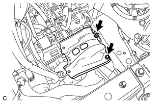
Remove the 2 bolts and battery carrier support.
32941
30.DISCONNECT OIL COOLER INLET HOSE
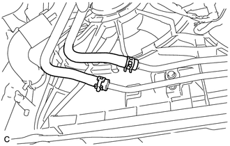
Remove the clamp and disconnect the oil cooler inlet hose.
32942
31.REMOVE OIL COOLER OUTLET HOSE
Remove the clamp and disconnect the oil cooler outlet hose.
16571C
32.DISCONNECT NO. 1 RADIATOR HOSE
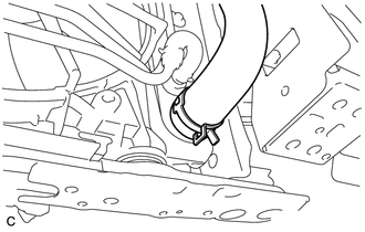
Remove the clamp and disconnect the No. 1 radiator hose.
16572D
33.DISCONNECT NO. 2 RADIATOR HOSE
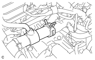
Remove the clamp and disconnect the No. 2 radiator hose.
87245A
34.DISCONNECT HEATER WATER INLET HOSE
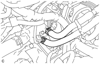
Disconnect the inlet hose from the heater unit pipe and water by-pass pipe.
87246B
35.DISCONNECT HEATER WATER OUTLET HOSE
Disconnect the outlet hose from the heater unit pipe and water by-pass pipe.
23826
36.DISCONNECT NO. 1 FUEL VAPOR FEED HOSE
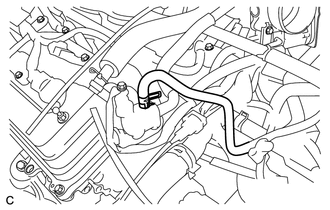
Remove the clamp and disconnect the No. 1 fuel vapor feed hose.
44774
37.DISCONNECT UNION TO CONNECTOR TUBE HOSE
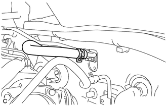
Remove the clamp and disconnect the union to connector tube hose.
33820B
38.DISCONNECT TRANSMISSION CONTROL CABLE
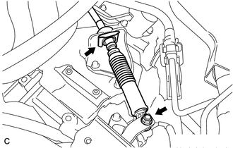
Remove the clip and nut, and separate the transmission cable from the transaxle.
89661
39.REMOVE ECM
82121
40.DISCONNECT ENGINE WIRE
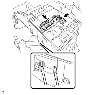
Remove the engine room relay block cover.
Disconnect the 2 connectors.
Using a screwdriver, unlock the 2 claws and separate the engine wire from the engine room relay block.
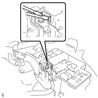
Using a screwdriver, unlock the 2 claws and loosen the bolt.
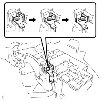
Slide the battery positive (+) cable as shown in the illustration.
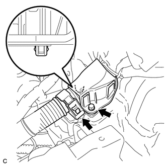
Remove the bolt and 2 clamps, and separate the wire harness protector from the bracket.
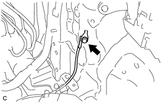
Remove the bolt and disconnect the ground cable from the body.
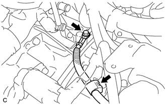
Disconnect the clamp, remove the bolt, and disconnect the ground cable.
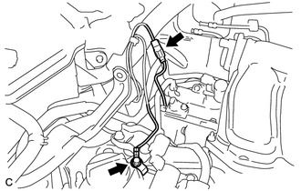
Disconnect the connector, remove the bolt, and disconnect the ground cable.
12327A
41.REMOVE NO. 2 ENGINE MOUNTING STAY RH
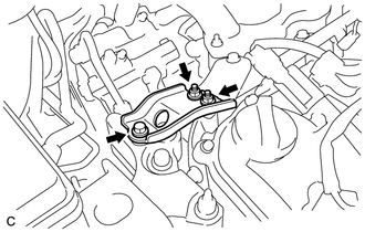
Remove the 2 bolts and No. 2 engine mounting stay RH.
88703
42.DISCONNECT DISCHARGE HOSE SUB-ASSEMBLY
88712
43.DISCONNECT NO. 1 COOLER REFRIGERANT SUCTION HOSE
77251B
44.DISCONNECT FUEL MAIN TUBE
Remove the No. 1 fuel pipe clamp.
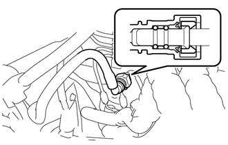
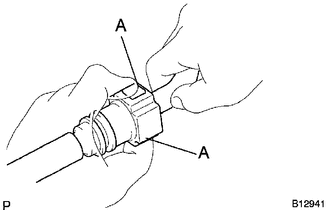
Disconnect the connector from the tube while pinching part A with your fingers as shown in the illustration.
- NOTICE:
- ·
Check for contamination in the pipe and around the connector. Clean if necessary and then disconnect the connector.
·Disconnect the connector by hand.
·Do not bend, fold or rotate the nylon tube.
·If the pipe and connector are stuck together, push and pull the connector until it becomes free.
·Put the pipe and connector ends in vinyl bags to prevent damage and contamination.
17420
45.REMOVE CENTER EXHAUST PIPE ASSEMBLY
17410
46.REMOVE FRONT EXHAUST PIPE ASSEMBLY
45259A
47.REMOVE COLUMN HOLE COVER SILENCER SHEET
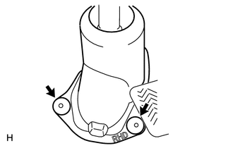
Fold back the floor carpet and remove the 2 clips and column hole cover silencer sheet.
45221
48.SEPARATE STEERING INTERMEDIATE SHAFT
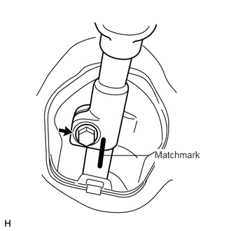
Place matchmarks on the steering intermediate shaft and steering gear.
Remove the bolt and separate the shaft.
45025D
49.DISCONNECT NO. 1 STEERING COLUMN HOLE COVER SUB-ASSEMBLY
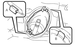
Push clip A in the direction of the center of the cover, and push down clip B to separate the steering column hole cover from the floor panel.
89542
50.DISCONNECT FRONT SPEED SENSOR
48810
51.SEPARATE FRONT STABILIZER LINK ASSEMBLY
52.DISCONNECT TIE ROD END SUB-ASSEMBLY
48069
53.SEPARATE FRONT SUSPENSION LOWER NO. 1 ARM SUB-ASSEMBLY LH
54.DISCONNECT FRONT AXLE HUB SUB-ASSEMBLY LH
12361A
55.REMOVE FRONT ENGINE MOUNTING INSULATOR
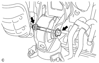
Remove the through bolt and nut.
12371A
56.REMOVE REAR ENGINE MOUNTING INSULATOR
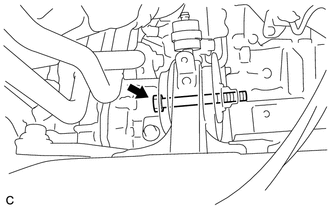
Remove the through bolt.
51218A
57.REMOVE FRONT SUSPENSION MEMBER REINFORCEMENT LH
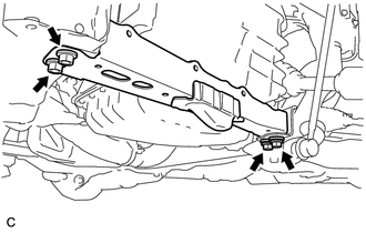
Remove the 4 bolts and reinforcement LH.
51217A
58.REMOVE FRONT SUSPENSION MEMBER REINFORCEMENT RH
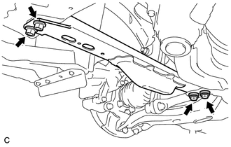
Remove the 4 bolts and reinforcement RH.
57104E
59.DISCONNECT FRONT CROSSMEMBER SUB-ASSEMBLY
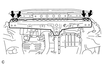
Remove the 4 bolts and disconnect the crossmember from the body.
51403B
60.REMOVE FRONT SUSPENSION MEMBER BRACE SUB-ASSEMBLY
Remove the 6 bolts and suspension member brace LH and RH.
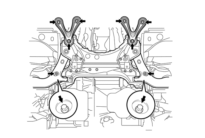
51201
61.REMOVE FRONT SUSPENSION CROSSMEMBER SUB-ASSEMBLY
Remove the 2 bolts and suspension crossmember.
62.SUSPEND ENGINE ASSEMBLY
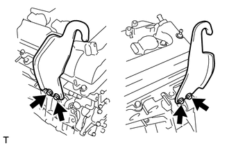
Install the No. 1 and No. 2 engine hangers with the bolts.
- Torque:
- 38 N*m (387 kgf*cm, 28 ft.*lbf)
| Item | Part No. |
|---|---|
| No. 1 engine hanger | 12281-31120 |
| No. 2 engine hanger | 12282-31100 |
| Bolt | 91671-10825 |
Attach the sling device to the engine hangers and chain block.
12305
63.REMOVE ENGINE MOUNTING INSULATOR RH
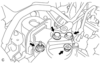
Remove the 2 nuts, 2 bolts and insulator RH.
12372A
64.REMOVE ENGINE MOUNTING INSULATOR LH
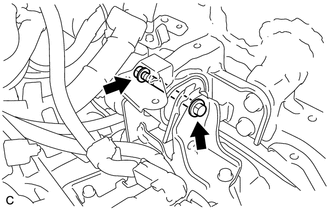
Remove the through bolt and nut.
11000
65.REMOVE ENGINE ASSEMBLY
Set an engine lifter underneath the engine.
- HINT:
-
Set wooden blocks or equivalent under the engine so that the engine is level.
Remove the sling device and chain block from the engine hangers.
Carefully remove the engine from the vehicle.
- NOTICE:
- ·
Make sure that the engine is clear of all wiring and hoses.
·While lowering the engine from the vehicle, do not allow it to contact the vehicle.
82121
66.REMOVE ENGINE WIRE
43410
67.REMOVE FRONT DRIVE SHAFT
Remove the front drive shaft LH and RH (See page Drivetrain>DRIVE SHAFT>FRONT DRIVE SHAFT ASSEMBLY>REMOVAL).
17118
68.REMOVE MANIFOLD STAY
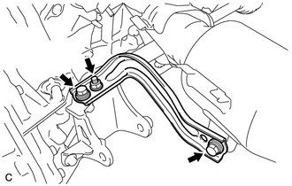
Remove the nut, 2 bolts and manifold stay.
12311A
69.REMOVE NO. 1 ENGINE MOUNTING BRACKET
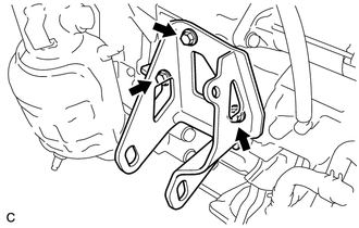
Remove the 3 bolts and No. 1 engine mounting bracket.
12321A
70.REMOVE NO. 2 ENGINE MOUNTING BRACKET
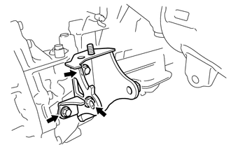
Remove the 3 bolts and No. 2 engine mounting bracket.
28100
71.REMOVE STARTER ASSEMBLY
11361J
72.REMOVE FLYWHEEL HOUSING UNDER COVER
17571
73.REMOVE NO. 1 EXHAUST PIPE SUPPORT BRACKET
Remove the 2 bolts and No. 1 exhaust pipe support bracket.
30500
74.REMOVE AUTOMATIC TRANSAXLE ASSEMBLY
Remove the automatic transaxle (See page Drivetrain>U660E (AUTOMATIC TRANSMISSION / TRANSAXLE)>AUTOMATIC TRANSAXLE ASSEMBLY>REMOVAL).
32101
75.REMOVE DRIVE PLATE
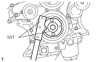
Using SST, hold the crankshaft pulley.
- SST
- 09213-70011 (09213-70020)
09330-00021
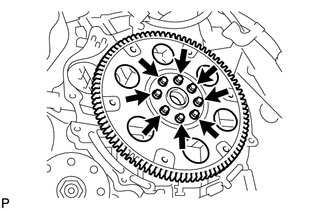
Remove the 8 bolts, rear spacer, drive plate and front spacer.
76.SECURE ENGINE
Secure the engine onto an engine stand with the bolts.
Remove the 2 engine hangers.
16361A
77.REMOVE FAN & GENERATOR V BELT
27415
78.REMOVE GENERATOR ASSEMBLY
88320
79.REMOVE COMPRESSOR AND MAGNETIC CLUTCH
17190
80.REMOVE INTAKE AIR SURGE TANK ASSEMBLY
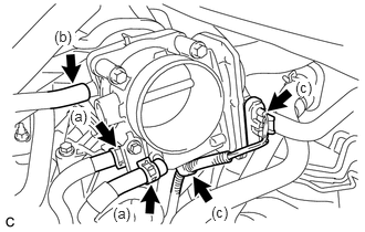
Disconnect the 2 water by-pass hoses from the throttle with motor body assembly.
Disconnect the vapor feed hose.
Disconnect the throttle with motor body assembly connector and clamp.
Disconnect the No. 1 ventilation hose.
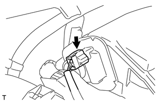
Disconnect the connector.
Remove the 4 bolts, No. 1 surge tank stay and throttle body bracket.
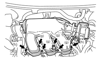
Using a 5 mm socket hexagon wrench, remove the 4 bolts.
Remove the 2 nuts and intake air surge tank.
Remove the gasket from the intake air surge tank.
19500
81.REMOVE IGNITION COIL ASSEMBLY
Remove the 6 bolts and 6 ignition coils.
12327A
82.REMOVE NO. 2 ENGINE MOUNTING STAY RH
Remove the bolt and No. 2 engine mounting stay RH.
17111
83.REMOVE INTAKE MANIFOLD
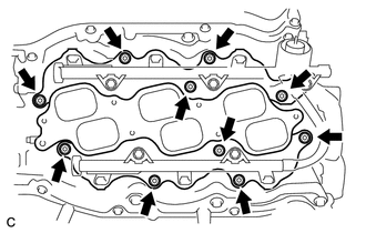
Uniformly loosen and remove the 6 bolts and 4 nuts.
Remove the intake manifold and 2 gaskets.
17104
84.REMOVE EXHAUST MANIFOLD SUB-ASSEMBLY RH
Disconnect the A/F sensor connector clamp.
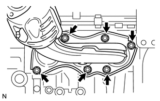
Uniformly loosen and remove the 6 nuts.
Remove the manifold and gasket.
85.REMOVE ENGINE OIL LEVEL DIPSTICK
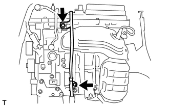
Remove the oil level dipstick.
Remove the 2 bolts, oil level dipstick guides No. 1 and No. 2.
Remove the O-rings from the oil level dipstick guide.
17119
86.REMOVE NO. 2 MANIFOLD STAY
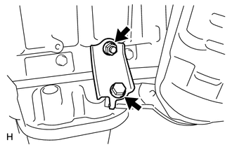
Remove the bolt, nut, and No. 2 manifold stay.
17168
87.REMOVE NO. 2 EXHAUST MANIFOLD HEAT INSULATOR
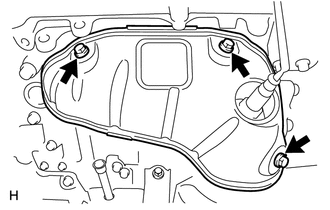
Remove the 3 bolts and No. 2 exhaust manifold heat insulator.
17105
88.REMOVE EXHAUST MANIFOLD SUB-ASSEMBLY LH
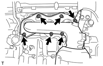
Uniformly loosen and remove the 6 nuts.
Remove the manifold and gasket.
43457
89.REMOVE DRIVE SHAFT BEARING BRACKET
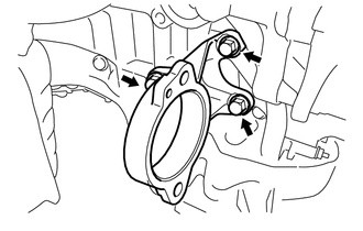
Remove the 3 bolts and bracket.
16620
90.REMOVE V-RIBBED BELT TENSIONER ASSEMBLY
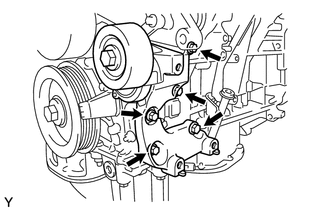
Remove the 5 bolts and V-ribbed belt tensioner assembly.
11322F
91.REMOVE NO. 2 TIMING GEAR COVER
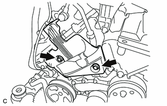
Remove the 2 bolts and No. 2 timing gear cover.
16604
92.REMOVE NO. 2 IDLER PULLEY SUB-ASSEMBLY
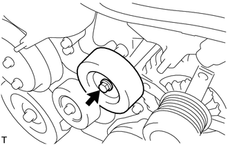
Remove the bolts, plates and No. 2 idler pulley sub-assembly.
16173
93.REMOVE WATER PUMP PULLEY
12315
94.REMOVE FRONT NO. 1 ENGINE MOUNTING BRACKET LH
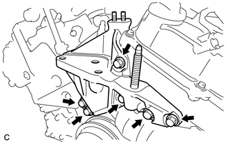
Remove the 6 bolts and No. 1 engine mounting bracket front LH.
86011A
95.REMOVE RADIO SETTING CONDENSER
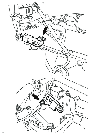
Remove the 2 bolts and 2 radio setting condensers.
25860
96.REMOVE NO. 1 VACUUM SWITCHING VALVE ASSEMBLY
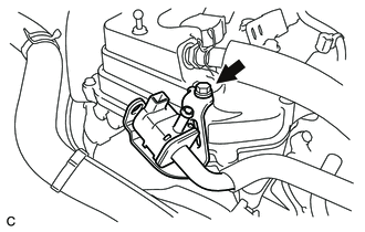
Remove the bolt and No. 1 vacuum switching valve.
83530
97.REMOVE ENGINE OIL PRESSURE SWITCH ASSEMBLY
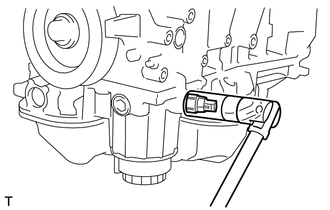
Using a 24 mm deep socket wrench, remove the engine oil pressure switch assembly.
89615
98.REMOVE KNOCK CONTROL SENSOR
89422
99.REMOVE ENGINE COOLANT TEMPERATURE SENSOR
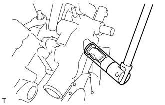
Using a 19 mm deep socket wrench, remove the engine coolant temperature sensor and gasket.