STEERING COLUMN STEERING COLUMN ASSEMBLY REMOVAL
CAUTION / NOTICE / HINT
- CAUTION:
-
Some of these service operations affect the SRS airbag system. Read the precautionary notices concerning the SRS airbag system before servicing the steering column (see page Vehicle Interior>SUPPLEMENTAL RESTRAINT SYSTEMS>AIRBAG SYSTEM>PRECAUTION).
PROCEDURE

 1.PLACE FRONT WHEELS FACING STRAIGHT AHEAD
28800J
2.DISCONNECT CABLE FROM NEGATIVE BATTERY TERMINAL
- CAUTION:
-
Wait at least 90 seconds after disconnecting the cable from the negative (-) battery terminal to prevent airbag and seat belt pretensioner activation.
45130
3.REMOVE STEERING PAD ASSEMBLY
45100
4.REMOVE STEERING WHEEL ASSEMBLY
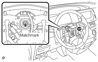
Remove the nut and place matchmarks on the steering wheel and steering column.
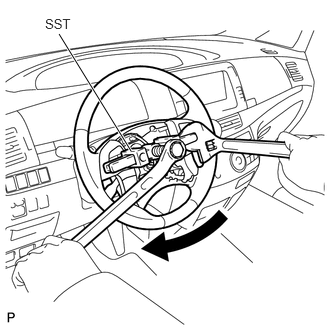
Using SST, remove the steering wheel.
- SST
- 09950-50013 (09951-05010, 09952-05010, 09953-05020, 09954-05021)
- NOTICE:
-
Apply a small amount of grease to the threads and tip of SST (center bolt) before use.
45286
5.REMOVE STEERING COLUMN COVER
- NOTICE:
-
Removing the steering column cover in the incorrect order will cause the steering column cover to break.
Release the tilt lever.
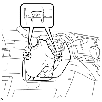
Push the right and left sides of the lower steering column cover, and disengage the 2 claws.
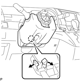
Insert fingers into the opening of the tilt lever of the lower steering column cover to disengage the claw.
- HINT:
-
Spread the claw to disengage it.
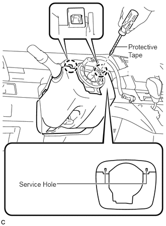
Using a screwdriver, insert the tip into each service hole to disengage the 2 claws and remove the lower steering column cover.
- HINT:
-
Tape the screwdriver tip before use.
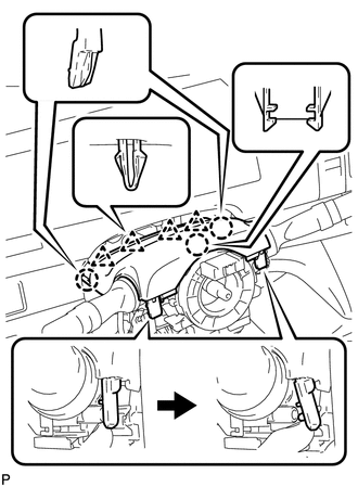
Disengage the 3 claws, 4 clips, and 2 pins, and remove the upper steering column cover.
6.REMOVE TURN SIGNAL SWITCH ASSEMBLY WITH SPIRAL CABLE
Disconnect all connectors from the turn signal switch with spiral cable.
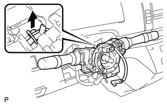
Detach the clamp shown in the illustration and remove the combination switch from the steering column.
55432B
7.REMOVE LOWER INSTRUMENT PANEL FINISH PANEL
with knee airbag :
Remove the lower instrument panel finish panel (see page Vehicle Interior>INTERIOR PANEL>LOWER INSTRUMENT PANEL>REMOVAL).
without knee airbag :
Remove the lower instrument panel finish panel (see page Vehicle Interior>INTERIOR PANEL>LOWER INSTRUMENT PANEL>REMOVAL).
45259A
8.REMOVE COLUMN HOLE COVER SILENCER SHEET
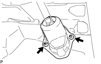
Turn back the floor carpet, and remove the 2 clips and column hole cover silencer sheet.
45260
9.REMOVE NO. 2 STEERING NTERMEDIATE SHAFT ASSEMBLY
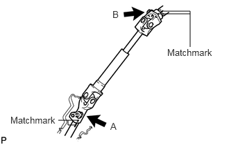
Place matchmarks on the steering intermediate shaft and steering gear.
Remove bolt A and detach the steering intermediate shaft from the steering gear.
Place matchmarks on the steering intermediate shaft and steering column.
Remove bolt B and detach the steering intermediate shaft from the steering column.
55302A
10.REMOVE UPPER INSTRUMENT PANEL SUB-ASSEMBLY (for LHD)
Remove the upper instrument panel (See page Vehicle Interior>INTERIOR PANEL>UPPER INSTRUMENT PANEL>REMOVAL).
45250
11.REMOVE STEERING COLUMN ASSEMBLY
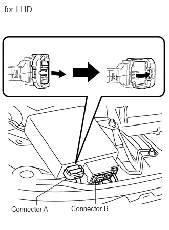
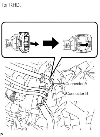
Disconnect connector A and connector B from the power steering ECU.
Disconnect all connectors and detach all wire harness clamps from the steering column.
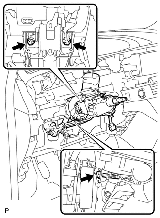
Remove the bolt, 2 nuts and steering column assembly.
- NOTICE:
-
Do not drop or strike the steering column. If dropped or struck, replace it with a new one.