Home › Vehicle Interior › DOOR LOCK › WIRELESS DOOR LOCK CONTROL SYSTEM › 2013.04–2016.05
RM24M0E _58 Vehicle Interior _059568 DOOR LOCK _0292010 WIRELESS DOOR LOCK CONTROL SYSTEM J

DOOR LOCK  WIRELESS DOOR LOCK CONTROL SYSTEM  Only Wireless Control Function is Inoperative  


DESCRIPTION

The door control receiver receives signals from the transmitter and sends these signals to the main body ECU. The main body ECU then controls all doors by sending lock / unlock signals to each door, and sends hazard flasher relay signals to the turn signal flasher relay (hazard warning lights), wireless door lock buzzer signal to the wireless door lock buzzer.

WIRING DIAGRAM
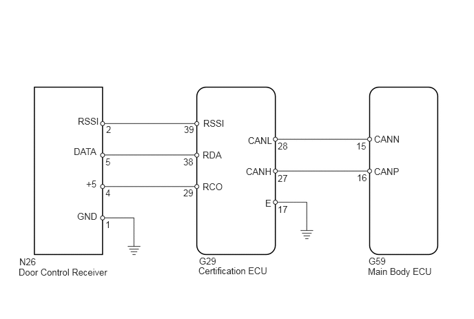
U185948E02
5.563,4.021 6.646,4.198 1.083,0.177 10 false Main Body ECU 1.177,1.75 1.521,1.969 0.344,0.219 10 false RSSI 0.281,4.031 1.719,4.208 1.438,0.177 10 false Door Control Receiver 3,4.01 4.083,4.188 1.083,0.177 10 false Certification ECU 3.073,1.781 3.563,2 0.49,0.219 10 false RSSI 1.115,2.208 1.521,2.427 0.406,0.219 10 false DATA 1.302,2.698 1.51,2.885 0.208,0.188 10 false +5 3.063,2.26 3.552,2.479 0.49,0.219 10 false RDA 3.063,2.74 3.552,2.958 0.49,0.219 10 false RCO 3.75,2.042 4.24,2.26 0.49,0.219 10 false CANL 4.01,2.99 4.323,3.177 0.313,0.188 10 false E 1.167,3.188 1.531,3.406 0.365,0.219 10 false GND 5.656,2.021 6.146,2.24 0.49,0.219 10 false CANN 3.719,2.51 4.208,2.729 0.49,0.219 10 false CANH 5.656,2.51 6.146,2.729 0.49,0.219 10 false CANP 3.01,3.865 3.427,4.01 0.417,0.146 10 false G29 4.198,3.083 4.458,3.25 0.26,0.167 10 false 17 1.594,2.365 1.854,2.531 0.26,0.167 10 false 5 2.771,2.833 3.031,3 0.26,0.167 10 false 29 1.604,1.875 1.823,2.052 0.219,0.177 10 false 2 2.771,2.365 3.031,2.531 0.26,0.167 10 false 38 1.594,2.833 1.854,3 0.26,0.167 10 false 4 1.594,3.313 1.854,3.479 0.26,0.167 10 false 1 0.292,3.875 0.875,4.042 0.583,0.167 10 false N26 5.385,2.125 5.646,2.292 0.26,0.167 10 false 15 4.198,2.615 4.458,2.781 0.26,0.167 10 false 27 4.198,2.125 4.458,2.292 0.26,0.167 10 false 28 5.396,2.604 5.656,2.771 0.26,0.167 10 false 16 2.781,1.875 3,2.052 0.219,0.177 10 false 39 5.573,3.865 5.875,4.01 0.302,0.146 10 false G59

PROCEDURE

1.CHECK WIRELESS DOOR LOCK CONTROL FUNCTIONS
a.

Check the wireless door lock control system function (see page Vehicle Interior>DOOR LOCK>WIRELESS DOOR LOCK CONTROL SYSTEM>OPERATION CHECK).

OK:

Each function of wireless door lock control system operates normally using transmitter switches.


NG

2.CHECK TRANSMITTER LED ILLUMINATION

OK

END

2.CHECK TRANSMITTER LED ILLUMINATION
a.

Check that the transmitter's LED illuminates 3 times when the is switch pressed 3 times.

OK:

Transmitter's LED illuminates 3 times when switch is pressed 3 times.


NG

3.REPLACE TRANSMITTER BATTERY

OK

4.CHECK ROOM NO. 1 LIGHT AND WIRELESS DOOR LOCK BUZZER
3.REPLACE TRANSMITTER BATTERY
a.

Temporarily replace the transmitter battery with a new or normally functioning one (see page Vehicle Interior>DOOR LOCK>TRANSMITTER BATTERY>REMOVAL).


b.

Check that the doors can be locked and unlocked using the transmitter switches.

OK:

Doors can be locked and unlocked with transmitter.


NG

4.CHECK ROOM NO. 1 LIGHT AND WIRELESS DOOR LOCK BUZZER

OK

END (TRANSMITTER BATTERY IS DEFECTIVE)

4.CHECK ROOM NO. 1 LIGHT AND WIRELESS DOOR LOCK BUZZER
a.

Check that the room No. 1 light illumination operates normally.


b.

Inspect the wireless door lock buzzer (see page Vehicle Interior>DOOR LOCK>WIRELESS DOOR LOCK CONTROL SYSTEM>No Answer-Back).

Result:
Result Proceed to
Room No. 1 light and wireless door lock buzzer is normal A
Room No. 1 light is malfunctioning B
Wireless door lock buzzer is malfunctioning C


A

5.SWITCH TO SELF DIAGNOSTIC MODE

B

GO TO LIGHTING SYSTEM

C

REPLACE WIRELESS DOOR LOCK BUZZER

5.SWITCH TO SELF DIAGNOSTIC MODE
a.

Switch to self-diagnostic mode.

i.

Connect the intelligent tester to the DLC3.


ii.

Turn the ignition switch on (IG) and turn the intelligent tester main switch ON.

HINT:

Refer to the intelligent tester operator's manual for further details.


iii.

Check that the system has switched to self-diagnostic mode by checking the room No. 1 light flash and wireless door lock buzzer sound patterns.
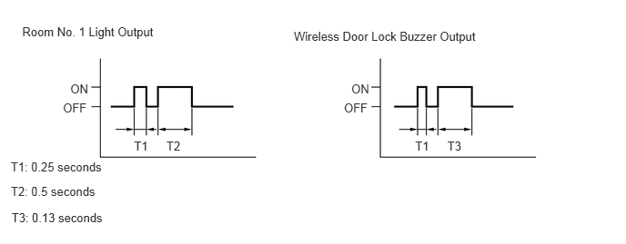
B148111E01
0.254,0.284 1.854,0.454 1.600,0.170 10 Room No. 1 Light Output 4.022,0.936 4.257,1.092 0.235,0.156 10 ON 0.721,1.16 1.038,1.316 0.318,0.156 10 OFF 0.805,0.936 1.039,1.092 0.235,0.156 10 ON 3.938,1.16 4.256,1.316 0.318,0.156 10 OFF 1.535,1.592 1.725,1.765 0.190,0.172 10 T1 5.122,1.592 5.313,1.765 0.190,0.172 10 T3 4.753,1.592 4.943,1.765 0.190,0.172 10 T1 1.905,1.592 2.095,1.765 0.190,0.172 10 T2 0.124,2.115 1.224,2.273 1.100,0.157 10 T2: 0.5 seconds 0.132,2.419 1.232,2.558 1.100,0.139 10 T3: 0.13 seconds 0.123,1.838 1.223,1.986 1.100,0.148 10 T1: 0.25 seconds 3.364,0.333 5.541,0.482 2.177,0.149 10 Wireless Door Lock Buzzer Output

OK:

Room No. 1 light flash and wireless door lock buzzer sound patterns are same as illustration.


OK

6.CHECK BY SELF DIAGNOSTIC MODE

NG

END (TRANSMITTER BATTERY IS DEFECTIVE)

6.CHECK BY SELF DIAGNOSTIC MODE
B141252E05
3.833,5.51 5.729,5.854 1.896,0.344 0.073,5.51 1.969,5.854 1.896,0.344 3.833,2.667 5.729,3.01 1.896,0.344 0.073,2.667 1.969,3.01 1.896,0.344 3.833,0.042 5.729,0.385 1.896,0.344 0.073,0.042 1.969,0.385 1.896,0.344 0.135,0.083 1.906,0.292 1.771,0.208 10 false Recognition code registered 0.135,2.708 1.906,2.875 1.771,0.167 10 false Unlatching code registered 0.083,5.896 1.615,6.104 1.531,0.208 10 false Room No. 1 light output 0.083,3.073 1.594,3.24 1.51,0.167 10 false Room No. 1 light output 0.083,0.458 1.594,0.625 1.51,0.167 10 false Room No. 1 light output 3.844,5.896 5.885,6.063 2.042,0.167 10 false Wireless door lock buzzer output 3.896,2.708 5.667,2.875 1.771,0.167 10 false Unlatching code registered 0.427,5.552 1.76,5.719 1.333,0.167 10 false No diagnosis outputs 4.094,5.552 5.458,5.719 1.365,0.167 10 false No diagnosis outputs 3.896,0.083 5.667,0.25 1.771,0.167 10 false Recognition code registered 3.844,0.448 5.885,0.615 2.042,0.167 10 false Wireless door lock buzzer output 3.844,3.063 5.885,3.229 2.042,0.167 10 false Wireless door lock buzzer output 4.333,0.802 4.615,0.948 0.281,0.146 10 false ON 0.615,1.26 0.969,1.406 0.354,0.146 10 false OFF 4.292,3.625 4.573,3.771 0.281,0.146 10 false ON 0.615,4.073 0.969,4.219 0.354,0.146 10 false OFF 0.677,3.625 0.958,3.771 0.281,0.146 10 false ON 4.219,4.073 4.573,4.219 0.354,0.146 10 false OFF 4.26,6.688 4.615,6.833 0.354,0.146 10 false OFF 0.615,6.688 0.969,6.833 0.354,0.146 10 false OFF 0.677,0.802 0.958,0.948 0.281,0.146 10 false ON 4.26,1.26 4.615,1.406 0.354,0.146 10 false OFF 5.063,1.542 5.26,1.688 0.198,0.146 10 false T3 1.813,1.542 2.01,1.688 0.198,0.146 10 false T2 1.417,1.542 1.615,1.688 0.198,0.146 10 false T1 5.427,1.542 5.625,1.688 0.198,0.146 10 false T2 5.021,4.375 6.542,4.615 1.521,0.24 10 false Wave is being received 1.396,4.375 2.917,4.615 1.521,0.24 10 false Wave is being received 0.094,1.719 1.26,1.875 1.167,0.156 10 false T1: 0.25 seconds 0.115,2.292 1.281,2.448 1.167,0.156 10 false T3: 0.13 seconds 0.104,2.021 1.125,2.177 1.021,0.156 10 false T2: 0.5 seconds

a.

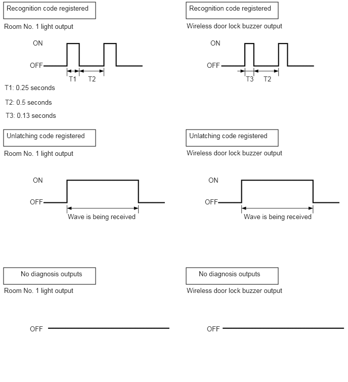
Inspect the diagnosis outputs when the door control transmitter switch is held down. The diagnosis outputs can be checked by the room No. 1 light flash and wireless door lock buzzer sound patterns.

Result
Result Proceed to
No diagnosis outputs A
Normal waves (light flash or buzzer sound patterns) for LOCK and UNLOCK switches are output B
Unmatching recognition code is output C


A

7.CHECK DOOR CONTROL TRANSMITTER (RESPONSE)

B

REPLACE MAIN BODY ECU

C

REGISTER RECOGNITION CODE

7.CHECK DOOR CONTROL TRANSMITTER (RESPONSE)
a.

Temporarily replace the door control transmitter with a new or normally functioning one.


b.

Press and hold down the door control transmitter's switch.


c.

Check that an unmatching recognition code is output.

OK:

Unmatching recognition code is output.


NG

8.CHECK DOOR CONTROL RECEIVER (OUTPUT)

OK

REPLACE WIRELESS DOOR LOCK TRANSMITTER

8.CHECK DOOR CONTROL RECEIVER (OUTPUT)
U185931E02
1.458,2.302 1.198,2.656 false 1.958,2.177 2.073,2.375 0.115,0.198 10 false 1 1.833,2.177 1.948,2.375 0.115,0.198 10 false 2 1.688,2.177 1.802,2.375 0.115,0.198 10 false 3 1.552,2.177 1.667,2.375 0.115,0.198 10 false 4 1.417,2.177 1.531,2.375 0.115,0.198 10 false 5 0.927,2.646 1.448,2.844 0.521,0.198 10 false DATA 1.594,0.698 1.927,0.896 0.333,0.198 10 false N26

a.

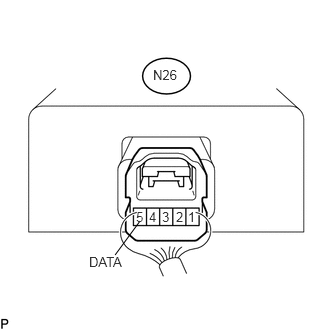
Measure the voltage of the connector.

Standard voltage:
Tester Connection Condition Specified Condition
N26-5 (DATA) - Body ground Ignition switch off, all doors closed and transmitter switch not pressed → pressed Below 1 V → 6 to 7 V → Below 1 V


OK

9.CHECK WIRE HARNESS (CERTIFICATION ECU - DOOR CONTROL RECEIVER)

NG

REPAIR OR REPLACE HARNESS OR CONNECTOR

9.CHECK WIRE HARNESS (CERTIFICATION ECU - DOOR CONTROL RECEIVER)
U188592E02
1.719,1.688 1.646,2.052 false 2.854,1.698 2.635,2.052 false 3.01,1.688 3.083,2.021 false 1.469,3.76 1.219,4.198 false 2.25,3.74 2.438,4.229 false 1.958,3.76 1.927,4.208 false 1.042,2.365 2.469,2.542 1.427,0.177 10 false Door Control Receiver 1.135,0.406 2.24,0.552 1.104,0.146 10 false Certification ECU 0.042,0.052 1.438,0.198 1.396,0.146 10 false Wire Harness Side: 1.656,0.823 1.958,0.979 0.302,0.156 10 false G29 1.604,2.719 1.875,2.896 0.271,0.177 10 false N26 1.458,2.073 1.781,2.25 0.323,0.177 10 false RCO 2.448,2.073 2.76,2.25 0.313,0.177 10 false RDA 2.948,2.052 3.292,2.229 0.344,0.177 10 false RSSI 2.438,4.24 2.823,4.417 0.385,0.177 10 false DATA 0.896,4.229 1.24,4.406 0.344,0.177 10 false RSSI 1.833,4.25 2.01,4.427 0.177,0.177 10 false +5

a.

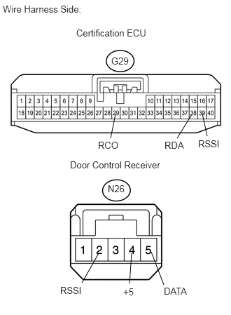
Disconnect the G29 ECU connector.


b.

Disconnect the N26 receiver connector.


c.

Measure the resistance or the wire harness side connectors.

Standard resistance:
Tester Connection Specified Condition
G29-29 (RCO) - N26-4 (+5) Below 1 Ω
G29-38 (RDA) - N26-5 (DATA) Below 1 Ω
G29-39 (RSSI) - N26-2 (RSSI) Below 1 Ω
G29-29 (RCO) - Body ground 10 kΩ or higher
G29-38 (RDA) - Body ground 10 kΩ or higher
G29-39 (RSSI) - Body ground 10 kΩ or higher


OK

10.CHECK WIRE HARNESS (MAIN BODY ECU - CERTIFICATION ECU)

NG

REPAIR OR REPLACE HARNESS OR CONNECTOR

10.CHECK WIRE HARNESS (MAIN BODY ECU - CERTIFICATION ECU)
B460039E01
1.5,0.583 1.917,0.833 0.417,0.25 1.5,3 1.917,3.25 0.417,0.25 1.583,2.292 1.917,1.917 false 2.5,2.292 2.083,1.917 false 1.25,4.333 1.479,3.948 false 1.833,4.333 1.615,3.948 false 0.052,0.052 1.458,0.313 1.406,0.26 10 false Wire Harness Side: 1.26,0.271 2.354,0.75 1.094,0.479 10 false Main Body ECU 1.552,0.625 2.115,0.885 0.563,0.26 10 false G59 1.323,2.292 1.885,2.552 0.563,0.26 10 false CANN 2.406,2.281 2.969,2.542 0.563,0.26 10 false CANP 1.156,2.667 2.458,3.01 1.302,0.344 10 false Certification ECU 1.563,3.042 2.125,3.302 0.563,0.26 10 false G29 0.938,4.344 1.5,4.604 0.563,0.26 10 false CANH 1.76,4.365 2.323,4.625 0.563,0.26 10 false CANL

a.

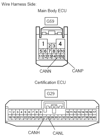
Disconnect the G59 and G29 ECU connectors.


b.

Measure the resistance of the wire harness side connectors.

Standard resistance:
Tester Connection Specified Condition
G59-15 (CANN) - G29-28 (CANL) Below 1 Ω
G59-16 (CANP) - G29-27 (CANH) Below 1 Ω
G59-15 (CANN) - Body ground 10 kΩ or higher
G59-16 (CANP) - Body ground 10 kΩ or higher


OK

11.REPLACE DOOR CONTROL RECEIVER (OPERATION)

NG

REPAIR OR REPLACE HARNESS OR CONNECTOR

11.REPLACE DOOR CONTROL RECEIVER (OPERATION)
a.

Temporarily replace the door control receiver with a new or normally functioning one.


b.

Check that the doors can be locked and unlocked by using the transmitter LOCK and UNLOCK switches.

OK:

Doors can be locked and unlocked with transmitter.


NG

12.REPLACE ECU AGGREGATION BOX (OPERATION)

OK

END (DOOR CONTROL RECEIVER IS DEFECTIVE)

12.REPLACE ECU AGGREGATION BOX (OPERATION)
a.

Temporarily replace the ECU aggregation box (certification ECU) with a new or normally functioning one.


b.

Check that the doors can be locked and unlocked by using the transmitter LOCK and UNLOCK switches.

OK:

Doors can be locked and unlocked with transmitter.


OK

END (CERTIFICATION ECU IS DEFECTIVE)

NG

REPLACE MAIN BODY ECU