Home › Vehicle Interior › DOOR LOCK › WIRELESS DOOR LOCK CONTROL SYSTEM › 2013.04–2016.05
RM24M0E _58 Vehicle Interior _059568 DOOR LOCK _0292010 WIRELESS DOOR LOCK CONTROL SYSTEM J

DOOR LOCK  WIRELESS DOOR LOCK CONTROL SYSTEM  No Answer-Back  


DESCRIPTION

In some cases, wireless door lock control functions are normal but the hazard warning lights and/or wireless door lock buzzer answer-back function(s) does not operate. In such cases, the certification ECU's hazard warning lights and wireless door lock buzzer signal outputs may be malfunctioning.

NOTICE:

Troubleshooting should be started after confirming that the customize status of the answer-back function has been switched ON.


WIRING DIAGRAM
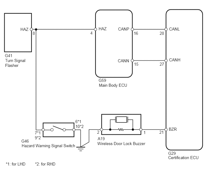
B143214E05
5.74,5.292 6.885,5.438 1.146,0.146 10 false Certification ECU 3.375,2.823 4.406,2.979 1.031,0.156 10 false Main Body ECU 0.177,1.979 0.948,2.313 0.771,0.333 10 false Turn Signal Flasher 3.365,0.896 3.833,1.104 0.469,0.208 10 false HAZ 0.698,0.917 1.167,1.125 0.469,0.208 10 false HAZ 4.031,0.906 4.708,1.104 0.677,0.198 10 false CANP 5.771,1.958 6.448,2.156 0.677,0.198 10 false CANH 5.771,0.906 6.448,1.104 0.677,0.198 10 false CANL 4.021,1.99 4.698,2.188 0.677,0.198 10 false CANN 5.76,4.323 6.167,4.521 0.406,0.198 10 false BZR 3.323,4.813 5.031,4.958 1.708,0.146 10 false Wireless Door Lock Buzzer 0.74,4.885 2.656,5.031 1.917,0.146 10 false Hazard Warning Signal Switch 5.438,4.427 5.667,4.625 0.229,0.198 10 false 21 5.448,2.104 5.771,2.281 0.323,0.177 10 false 27 5.448,1.052 5.771,1.229 0.323,0.177 10 false 28 5.74,5.146 6.031,5.292 0.292,0.146 10 false G29 4.896,4.438 5.042,4.604 0.146,0.167 10 false 1 3.313,4.427 3.458,4.583 0.146,0.156 10 false 2 3.333,4.646 3.677,4.833 0.344,0.188 10 false A19 3.365,2.656 3.667,2.813 0.302,0.156 10 false G59 3.083,1.042 3.24,1.229 0.156,0.188 10 false 4 4.563,1.052 4.802,1.24 0.24,0.188 10 false 16 4.573,2.104 4.813,2.271 0.24,0.167 10 false 15 1.115,1.052 1.313,1.25 0.198,0.198 10 false 8 0.167,1.813 0.479,1.958 0.313,0.146 10 false G41 0.729,4.729 1.156,4.896 0.427,0.167 10 false G46 1.188,4.448 1.438,4.781 0.25,0.333 10 false 7*1 9*2 2.573,4.063 2.875,4.396 0.302,0.333 10 false 6*1 10*2 0.198,5.51 0.948,5.823 0.75,0.313 10 false *1: for LHD 1.198,5.51 1.948,5.823 0.75,0.313 10 false *2: for RHD

PROCEDURE

1.CHECK WIRELESS DOOR LOCK CONTROL FUNCTION
a.

Check the wireless door lock control functions by operating the transmitter switch.

Result:
Result Proceed to
Wireless door lock functions are normal but hazard warning lights answer-back does not occur A
Wireless door lock functions are normal but wireless door lock buzzer answer-back does not occur B
Doors cannot be locked and unlocked with transmitter C


A

2.PERFORM ACTIVE TEST USING INTELLIGENT TESTER (TURN SIGNAL FLASHER)

B

6.PERFORM ACTIVE TEST USING INTELLIGENT TESTER (WIRELESS DOOR LOCK BUZZER)

C

2.PERFORM ACTIVE TEST USING INTELLIGENT TESTER (TURN SIGNAL FLASHER)
a.

Select the Active Test, use the intelligent tester to generate a control command, and then check that the hazard warning lights flash.

Main body ECU:
Item Test Details Diagnostic Note
Hazard Turn turn signal flasher ON / OFF -


OK:

Hazard warning lights are turned ON / OFF.


NG

3.CHECK HAZARD WARNING LIGHT

OK

REPLACE MAIN BODY ECU

3.CHECK HAZARD WARNING LIGHT
a.

Check that the hazard warning lights flash continuously when the hazard warning signal switch is pressed.

OK:

Hazard warning lights flash continuously.


OK

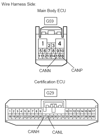
4.CHECK WIRE HARNESS (MAIN BODY ECU - CERTIFICATION ECU)

NG

4.CHECK WIRE HARNESS (MAIN BODY ECU - CERTIFICATION ECU)
B460039E01
1.5,0.583 1.917,0.833 0.417,0.25 1.5,3 1.917,3.25 0.417,0.25 1.583,2.292 1.917,1.917 false 2.5,2.292 2.083,1.917 false 1.25,4.333 1.479,3.948 false 1.833,4.333 1.615,3.948 false 0.052,0.052 1.458,0.313 1.406,0.26 10 false Wire Harness Side: 1.26,0.271 2.354,0.75 1.094,0.479 10 false Main Body ECU 1.552,0.625 2.115,0.885 0.563,0.26 10 false G59 1.323,2.292 1.885,2.552 0.563,0.26 10 false CANN 2.406,2.281 2.969,2.542 0.563,0.26 10 false CANP 1.156,2.667 2.458,3.01 1.302,0.344 10 false Certification ECU 1.563,3.042 2.125,3.302 0.563,0.26 10 false G29 0.938,4.344 1.5,4.604 0.563,0.26 10 false CANH 1.76,4.365 2.323,4.625 0.563,0.26 10 false CANL

a.

Disconnect the G59 and G29 ECU connectors.


b.

Measure the resistance of the wire harness side connectors.

Standard resistance:
Tester Connection Specified Condition
G59-15 (CANN) - G29-28 (CANL) Below 1 Ω
G59-16 (CANP) - G29-27 (CAH) Below 1 Ω
G59-15 (CANN) - Body ground 10 kΩ or higher
G59-16 (CANP) - Body ground 10 kΩ or higher


OK

5.REPLACE ECU AGGREGATION BOX (OPERATION)

NG

REPAIR OR REPLACE HARNESS OR CONNECTOR

5.REPLACE ECU AGGREGATION BOX (OPERATION)
a.

Temporarily replace the ECU aggregation box (certification ECU) with a new or normally functioning one.


b.

Check that the hazard warning lights flash continuously when the transmitter LOCK and UNLOCK switch is pressed.

OK:

Hazard warning lights flash continuously.


OK

END (CERTIFICATION ECU IS DEFECTIVE)

NG

REPLACE MAIN BODY ECU

6.PERFORM ACTIVE TEST USING INTELLIGENT TESTER (WIRELESS DOOR LOCK BUZZER)
a.

Select the Active Test, use the intelligent tester to generate a control command, and then check that the wireless door lock buzzer sounds.

Certification ECU:
Item Test Details Diagnostic Note
Wireless buzzer Wireless door lock buzzer sounds ON / OFF -


OK:

Wireless door lock buzzer sounds ON / OFF.


NG

7.INSPECT WIRELESS DOOR LOCK BUZZER

OK

REPLACE ECU AGGREGATION BOX (CERTIFICATION ECU)

7.INSPECT WIRELESS DOOR LOCK BUZZER
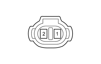
B127185

a.

Measure the resistance between terminals 1 and 2 of the buzzer.

OK:

Approximately 1 kΩ.


OK

8.CHECK WIRE HARNESS (WIRELESS DOOR LOCK BUZZER - CERTIFICATION ECU AND BODY GROUND)

NG

REPLACE WIRELESS DOOR LOCK BUZZER

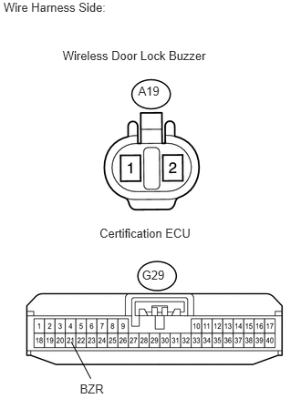
8.CHECK WIRE HARNESS (WIRELESS DOOR LOCK BUZZER - CERTIFICATION ECU AND BODY GROUND)
U188705E01
0.04,0 1.453,0.177 1.413,0.177 10 Wire Harness Side: 0.715,0.557 2.437,0.703 1.722,0.145 10 Wireless Door Lock Buzzer 1.578,0.961 1.880,1.100 0.302,0.139 10 A19 1.621,3.058 1.937,3.280 0.316,0.222 10 G29 1.136,2.581 2.264,2.737 1.128,0.156 10 Certification ECU 0.912,4.368 1.245,4.528 0.333,0.159 10 BZR 0.814,3.909 1.037,4.33 false

a.

Disconnect the A19 buzzer connector.


b.

Disconnect the G29 ECU connector.


c.

Measure the resistance of the wire harness side connectors.

Standard resistance:
Tester Connection Specified Condition
A19-1 - G29-21 (BZR) Below 1 Ω
A19-2 - Body ground Below 1 Ω
A19- - Body ground 10 kΩ or higher


OK

REPLACE ECU AGGREGATION BOX (CERTIFICATION ECU)

NG

REPAIR OR REPLACE HARNESS OR CONNECTOR