2AZ-FE STARTING ENGINE SWITCH INSTALLATION
PROCEDURE

 89611
1.INSTALL ENGINE SWITCH
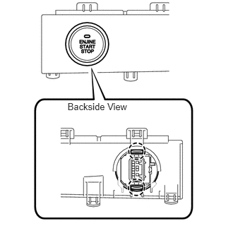
Attach the 2 claws to install the switch.
Connect the switch connector.
55474B
2.INSTALL INSTRUMENT CLUSTER FINISH PANEL GARNISH
55041B
3.INSTALL NO. 1 INSTRUMENT PANEL BOX DOOR SUB-ASSEMBLY
55650
4.INSTALL NO. 1 INSTRUMENT PANEL REGISTER ASSEMBLY
55042B
5.INSTALL NO. 2 INSTRUMENT PANEL BOX DOOR SUB-ASSEMBLY
55660
6.INSTALL NO. 2 INSTRUMENT PANEL REGISTER ASSEMBLY
7.INSTALL NAVIGATION RECEIVER ASSEMBLY WITH BRACKET (for Navigation Receiver Type)
55414A
8.INSTALL INSTRUMENT CLUSTER FINISH PANEL END (w/o Navigation System)
55420A
9.INSTALL INSTRUMENT CLUSTER FINISH PANEL CENTER ASSEMBLY
10.CONNECT CABLE TO NEGATIVE BATTERY TERMINAL
11.PERFORM INITIALIZATION
Perform initialization (see page General>INTRODUCTION>REPAIR INSTRUCTION>INITIALIZATION).
- NOTICE:
-
Certain systems need to be initialized after disconnecting and reconnecting the cable from the negative (-) battery terminal.