INTERIOR PANEL UPPER INSTRUMENT PANEL INSTALLATION
PROCEDURE

 55302A
1.INSTALL UPPER INSTRUMENT PANEL
Connect the wire.
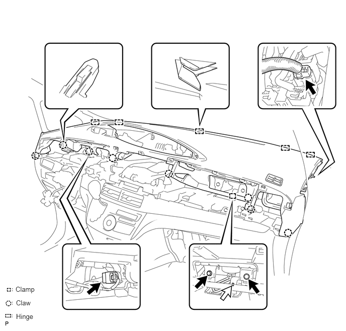
Engage the 9 claws and 5 guides.
Install the 2 bolts the passenger airbag.
- Torque:
- 20 N*m (204 kgf*cm, 15 ft.*lbf)
Connect the connectors and clamps, and install to upper instrument panel.
2.CONNECT FRONT PASSENGER AIRBAG CONNECTOR
62212
3.INSTALL FRONT PILLAR GARNISH LH (w/ Curtain Shield Airbag)
62212
4.INSTALL FRONT PILLAR GARNISH LH (w/o Curtain Shield Airbag)
62226
5.INSTALL FRONT PILLAR GARNISH LOWER LH
62211
6.INSTALL FRONT PILLAR GARNISH RH (w/ Curtain Shield Airbag)
- HINT:
-
Perform the same procedure as for the LH side.
62211
7.INSTALL FRONT PILLAR GARNISH RH (w/o Curtain Shield Airbag)
- HINT:
-
Perform the same procedure as for the LH side.
62225A
8.INSTALL FRONT PILLAR GARNISH LOWER RH
Perform the same procedure as for the LH side.
55042B
9.INSTALL NO. 2 INSTRUMENT PANEL BOX DOOR SUB-ASSEMBLY
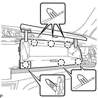
Engage the 6 claws to the install box door.
55660
10.INSTALL NO. 2 INSTRUMENT PANEL REGISTER ASSEMBLY
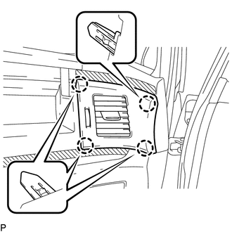
Engage the 4 claws to the install the register.
55041B
11.INSTALL NO. 1 INSTRUMENT PANEL BOX DOOR SUB-ASSEMBLY
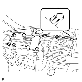
Engage the 10 claws to install the box door.
55650
12.INSTALL NO. 1 INSTRUMENT PANEL REGISTER ASSEMBLY
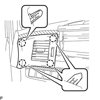
Engage the 4 clips to install the register.
55522B
13.INSTALL RADIO TUNER OPENING COVER (w/o Radio Receiver)
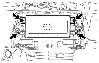
Install the opening cover with the 4 screws.
14.INSTALL RADIO RECEIVER ASSEMBLY WITH BRACKET (for Radio Receiver Type)
15.INSTALL NAVIGATION RECEIVER ASSEMBLY WITH BRACKET (for Navigation Receiver Type)
55414A
16.INSTALL INSTRUMENT CLUSTER FINISH PANEL END (w/o Navigation System)
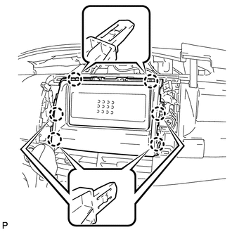
Engage the 6 claws to install the panel end.
55420A
17.INSTALL INSTRUMENT CLUSTER FINISH PANEL CENTER ASSEMBLY
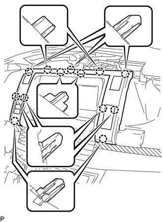
Engage the 13 clips to install the panel center and then connect the connectors.
18.INSTALL TURN SIGNAL SWITCH ASSEMBLY WITH SPIRAL CABLE
45286
19.INSTALL STEERING COLUMN COVER
45100
20.INSTALL STEERING WHEEL ASSEMBLY
45130
21.INSTALL STEERING PAD ASSEMBLY
45186
22.INSTALL NO. 2 STEERING WHEEL LOWER COVER
45187
23.INSTALL NO. 3 STEERING WHEEL LOWER COVER
55404C
24.INSTALL INSTRUMENT CLUSTER FINISH PANEL SUB-ASSEMBLY
Engage the 5 claws and 3 guides to install the finish panel.
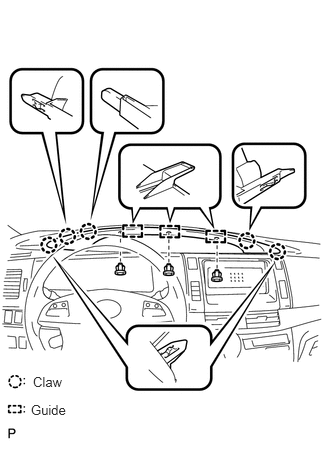
Install the 3 clips.
25.CONNECT CABLE TO NEGATIVE BATTERY TERMINAL
26.CHECK SRS WARNING LIGHT
27.PERFORM INITIALIZATION
Perform initialization (See page General>INTRODUCTION>REPAIR INSTRUCTION>INITIALIZATION).
- NOTICE:
-
Certain systems need to be initialized after disconnecting and reconnecting the cable from the negative (-) battery terminal.