BRAKE CONTROL / DYNAMIC CONTROL SYSTEMS VEHICLE STABILITY CONTROL SYSTEM C0273/13 Open in ABS Motor Relay Circuit
DESCRIPTION
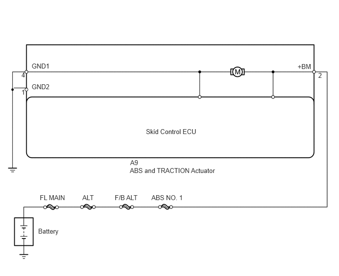
The ABS motor relay is included in the ABS and TRACTION actuator.
While the ABS, TRC or VSC is operating, the skid control ECU turns the ABS motor relay on and activates the pump motor in the ABS and TRACTION actuator.
These DTCs may be stored if the motor relay (+BM) voltage becomes lower than the DTC detection condition due to insufficient output from the battery or alternator.
| DTC No. | DTC Detection Condition | Trouble Area |
|---|---|---|
| C0273/13 | When either condition below is met:
1.
When the motor relay is actuated, voltage is not supplied to the pump motor within 0.08 second. 2.
When the motor relay is not actuated, voltage in the pump motor is high for 2.5 seconds or more. 3.
Voltage in the pump motor is low for 0.04 second or more and the pump is activated for 0.7 second 3 times. At the 3rd time, the pump motor becomes inoperative due to open circuit. |
·
ABS motor relay ·
ABS NO. 1 H-fuse ·
ABS and TRACTION actuator ·
Wire Harness |
- HINT:
-
DTCs C0273/13: The skid control ECU begins to detect these DTCs when the vehicle speed exceeds 15 km/h (9 mph).
WIRING DIAGRAM
PROCEDURE
Select the Active Test, generate a control command, and then check that the ABS motor relay operates.
| Tester Display | Test Part | Control Range | Diagnostic Note |
|---|---|---|---|
| Motor Relay | ABS motor relay | Relay ON/OFF | Operating sound of motor can be head |
- OK:
The operation sound of the ABS motor can be heard.
NG
OK
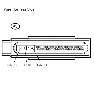
Disconnect the A9 ECU connector.
Measure the voltage of the wire harness side connector.
- Standard voltage:
Tester Connection Specified Condition A9-2 (+BM) - Body ground 10 to 14 V
Measure the resistance of the wire harness side connector.
- Standard resistance:
Tester Connection Specified Condition A9-4 (GND1) - Body ground Below 1 Ω A9-1 (GND2) - Body ground Below 1 Ω
OK
NG
Clear the DTC(s) (see page Brake>BRAKE CONTROL / DYNAMIC CONTROL SYSTEMS>VEHICLE STABILITY CONTROL SYSTEM>DTC CHECK / CLEAR).
Start the engine.
Drive the vehicle at 15 km/h (9 mph) or more to activate the initial check.
Check if the same DTC(s) is output (see page Brake>BRAKE CONTROL / DYNAMIC CONTROL SYSTEMS>VEHICLE STABILITY CONTROL SYSTEM>DTC CHECK / CLEAR).
| Result | Proceed to |
|---|---|
| DTC is output (for 2AZ-FE) | A |
| DTC is output (for 2GR-FE) | B |
| DTC is not output | C |
A
B
C