Home › Brake › BRAKE CONTROL / DYNAMIC CONTROL SYSTEMS › VEHICLE STABILITY CONTROL SYSTEM › 2013.04–2014.09
RM24M0E _54 Brake _059583 BRAKE CONTROL / DYNAMIC CONTROL SYSTEMS _0292158 VEHICLE STABILITY CONTROL SYSTEM C

BRAKE CONTROL / DYNAMIC CONTROL SYSTEMS  VEHICLE STABILITY CONTROL SYSTEM  C1241/41  Low Battery Positive Voltage  


DESCRIPTION

When there is an abnormality in the power supply circuit of the ABS and TRACTION actuator (skid control ECU), the skid control ECU sets a DTC and the operation is prohibited by the fail-safe function. This DTC is set when the voltage supplied to terminal IG1 is outside the DTC detection threshold, due to abnormalities of the battery, power source circuits or charging circuits such as the alternator circuit.

The fail-safe function is canceled when the voltage to terminal IG1 returns to normal.

DTC No. DTC Detection Condition Trouble Area
C1241/41 When one of following conditions is met:
1.

Battery voltage is 17.4 V or more.

2.

Battery voltage is 9.8 V or less when ABS does not operate.

3.

Battery voltage is 9.4 V or less when ABS operates.


·

Battery

·

Charging system

·

Power source circuit

·

Internal power supply circuit of skid control ECU


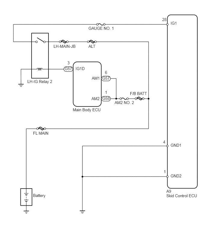
WIRING DIAGRAM

C137933E09
5.906,0.719 6.219,0.885 0.313,0.167 10 false IG1 5.76,6.542 6.021,6.698 0.26,0.156 10 false A9 3.063,0.896 4.052,1.063 0.99,0.167 10 false GAUGE NO. 1 0.948,2.74 1.906,2.896 0.958,0.156 10 false LH-IG Relay 2 3.063,1.521 3.396,1.771 0.333,0.25 10 false ALT 2.615,2.292 3.135,2.521 0.521,0.229 10 false IG1D 3.177,2.625 3.635,2.813 0.458,0.188 10 false AM1 3.167,3.333 3.656,3.521 0.49,0.188 10 false AM2 3.969,3.469 4.74,3.625 0.771,0.156 10 false AM2 NO. 2 4.5,3.156 5.188,3.313 0.688,0.156 10 false F/B BATT 1.146,4.531 1.771,4.729 0.625,0.198 10 false FL MAIN 1.146,6.688 1.771,6.885 0.625,0.198 10 false Battery 5.906,4.948 6.385,5.26 0.479,0.313 10 false GND1 5.906,6.01 6.458,6.281 0.552,0.271 10 false GND2 2.521,3.719 3.573,3.917 1.052,0.198 10 false Main Body ECU 1.854,1.521 2.719,1.688 0.865,0.167 10 false LH-MAIN-JB 2.24,2.292 2.542,2.479 0.302,0.188 10 false G57 3.542,2.625 3.844,2.813 0.302,0.188 10 false G57 3.542,3.323 3.844,3.51 0.302,0.188 10 false G58 3.635,2.427 3.802,2.573 0.167,0.146 10 false 6 5.615,0.594 5.813,0.74 0.198,0.146 10 false 28 2.333,2.094 2.5,2.24 0.167,0.146 10 false 3 3.635,3.115 3.802,3.26 0.167,0.146 10 false 1 5.667,5.865 5.833,6.01 0.167,0.146 10 false 1 5.646,4.833 5.813,4.979 0.167,0.146 10 false 4 5.76,6.698 6.906,6.885 1.146,0.188 10 false Skid Control ECU

PROCEDURE

1.INSPECT FUSE (GAUGE NO. 1)
a.

Remove the GAUGE NO. 1 fuse from the instrument panel junction block.


b.

Measure the resistance of the fuse.

Standard resistance:

Below 1 Ω


OK

2.INSPECT BATTERY

NG

REPLACE FUSE

2.INSPECT BATTERY
a.

Check the battery voltage.

Standard voltage:

10 to 14 V


OK

3.CHECK WIRE HARNESS (SKID CONTROL ECU - BATTERY)

NG

CHECK CHARGING SYSTEM

3.CHECK WIRE HARNESS (SKID CONTROL ECU - BATTERY)
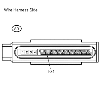
a.
U189323E02
1.573,1.792 1.698,2.313 false 0.135,0.25 1.427,0.396 1.292,0.146 10 false Wire Harness Side: 0.469,0.885 0.667,1.031 0.198,0.146 10 false A9 1.625,2.323 1.885,2.49 0.26,0.167 10 false IG1

Disconnect the A9 ECU connector.


b.

Measure the voltage of the wire harness side connector.

Standard voltage:
Tester Connection Condition Specified Condition
A9-28 (IG1) - Body ground Engine switch on (IG) 10 to 14 V


OK

4.CHECK WIRE HARNESS (SKID CONTROL ECU - BODY GROUND)

NG

REPAIR OR REPLACE HARNESS OR CONNECTOR

4.CHECK WIRE HARNESS (SKID CONTROL ECU - BODY GROUND)
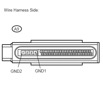
a.
U189324E02
1.219,1.76 1.344,2.281 false 0.74,1.76 0.604,2.24 false 0.135,0.25 1.427,0.396 1.292,0.146 10 false Wire Harness Side: 0.469,0.885 0.667,1.031 0.198,0.146 10 false A9 1.167,2.281 1.594,2.448 0.427,0.167 10 false GND1 0.354,2.292 0.781,2.458 0.427,0.167 10 false GND2

Disconnect the A9 ECU connector.


b.

Measure the resistance of the wire harness side connector.

Standard resistance:
Tester Connection Specified Condition
A9-4 (GND1) - Body ground Below 1 Ω
A9-1 (GND2) - Body ground Below 1 Ω


OK

5.RECONFIRM DTC

NG

REPAIR OR REPLACE HARNESS OR CONNECTOR

5.RECONFIRM DTC

b.

Drive the vehicle at 40 km/h (25 mph) or more for several seconds.


c.

Check if the same DTC is output (see page Brake>BRAKE CONTROL / DYNAMIC CONTROL SYSTEMS>VEHICLE STABILITY CONTROL SYSTEM>DTC CHECK / CLEAR).

Result
Result Proceed to
DTC is output (for 2AZ-FE) A
DTC is output (for 2GR-FE) B
DTC is not output C


A

B

REPLACE ABS AND TRACTION ACTUATOR ASSEMBLY

C

END