METER / GAUGE / DISPLAY COMBINATION METER INSTALLATION
PROCEDURE

 83809
1.INSTALL COMBINATION METER SUB-ASSEMBLY
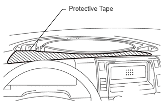
Apply protective tape under the instrument panel.
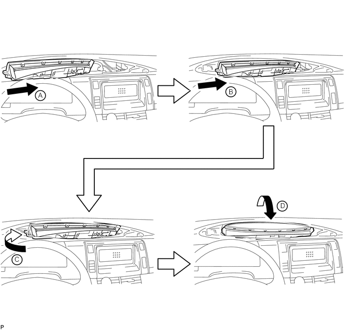
Slide the combination meter in the direction of arrow A with the glass facing upward.
Slide the right end of the combination meter in the direction of arrow B, and insert it into the upper instrument panel.
Slide the left end of the combination meter in the direction of arrow C so that the combination meter is inside the upper instrument panel.
Rotate the combination meter in the direction of arrow D.
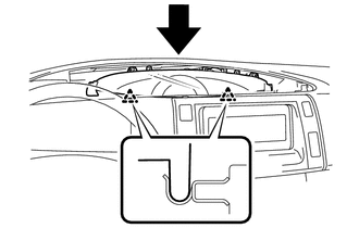
Attach the 2 clips to completely install the combination meter.
Connect the connector.
Install the 2 screws.
83856
2.INSTALL NO. 2 COMBINATION METER BRACKET
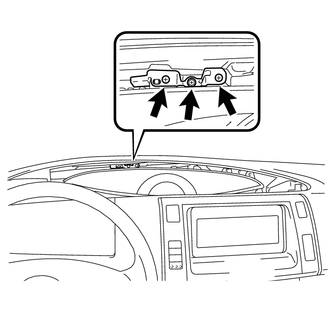
Install the bracket with the 3 screws.
83855
3.INSTALL NO. 1 COMBINATION METER BRACKET
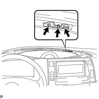
Install the bracket with the 3 screws.
55404C
4.INSTALL INSTRUMENT CLUSTER FINISH PANEL
28800
5.CONNECT CABLE TO NEGATIVE BATTERY TERMINAL
6.CHECK SRS WARNING LIGHT
Check the SRS warning light (see page Vehicle Interior>SUPPLEMENTAL RESTRAINT SYSTEMS>AIRBAG SYSTEM>DIAGNOSIS SYSTEM).
7.PERFORM INITIALIZATION
Perform initialization (see page General>INTRODUCTION>REPAIR INSTRUCTION>INITIALIZATION).
- NOTICE:
-
Certain systems need to be initialized after disconnecting and reconnecting the cable from the negative (-) battery terminal.