2011-2016 FJ Cruiser · Service Manual HEATER & AIR CONDITIONING SYSTEM

REMOVAL

Removal / installation · Vehicles built Nov 2010 – Jul 2012

Versions by build date: Jul 2007 – Jul 2009 Aug 2009 – Oct 2010 Nov 2010 – Jul 2012 Aug 2012 – Jul 2013 from Aug 2013

CAUTION:
Some of these service operations affect the SRS airbag system. Read the precautionary notices concerning the SRS airbag system before servicing (Click here).


1. RECOVER REFRIGERANT FROM REFRIGERATION SYSTEM
  1. Start up the engine.

  1. Switch A/C ON.

  1. Turn the blower switch to ON.

  1. Operate the cooler compressor with an engine speed of approximately 1,000 rpm for 5 to 6 minutes to circulate the refrigerant and collect the remaining compressor oil from each component, in the cooler compressor.

  1. Stop the engine.

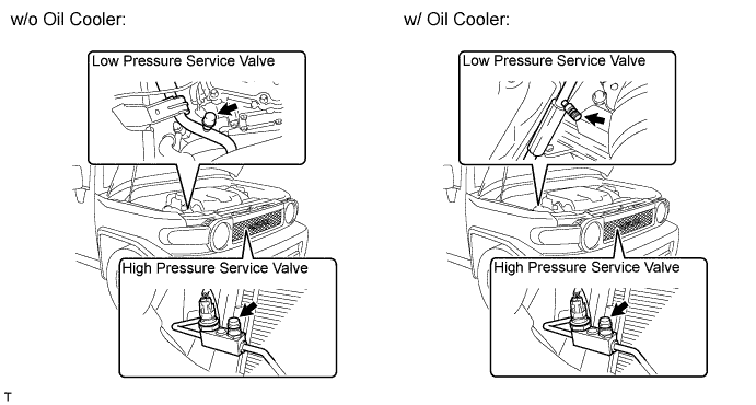
  1. Remove the caps from the service valves on the refrigerant line.

    I104027E01

  1. Connect the refrigerant recovery unit.

  1. Recover the refrigerant from the air conditioning system using a refrigerant recovery unit.

    NOTICE:
    Use the refrigerant recovery unit in accordance with the manufacturer's instruction manual.


2. DRAIN ENGINE COOLANT

CAUTION:
Do not remove the radiator cap while the engine and radiator are still hot. Pressurized, hot engine coolant and steam may be released and cause serious burns.

  1. Remove the service hole cover from the engine under cover.

  1. A070279E02
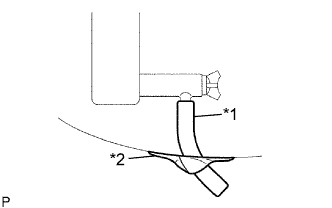
    Install a vinyl hose onto the drain on the radiator side.
    Text in Illustration 
    *1
    Vinyl Hose
    *2
    Tape

  1. Fix the vinyl hose with tape.

    A220213E01

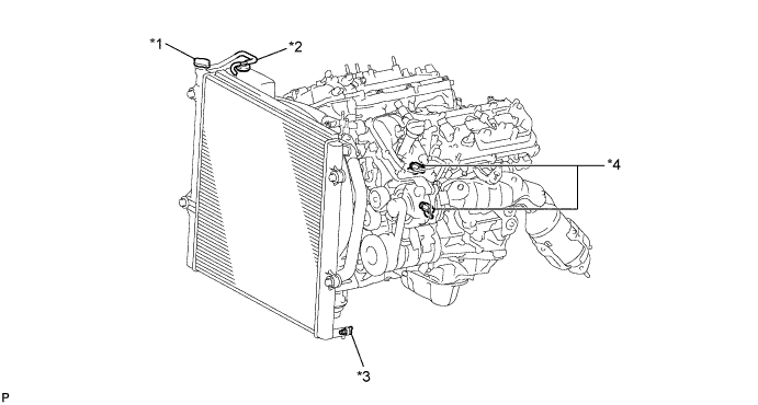
    Text in Illustration 
    *1
    Radiator Cap
    *2
    Reservoir Cap
    *3
    Radiator Drain Cock Plug
    *4
    Cylinder Block Drain Cock Plug

  1. Loosen the radiator drain cock plug.

  1. Remove the radiator cap and drain the coolant.

    HINT:
    Collect the coolant in a container and dispose of it according to the regulations in your area.

  1. Loosen the 2 cylinder block drain cock plugs and drain the coolant from the engine.

    NOTICE:
    If coolant is not drained from the radiator drain cock plug, cylinder block drain cock plugs and radiator reservoir, clogging in the radiator or coolant leakage from the seal of water pump may result.


3. DISCONNECT CABLE FROM NEGATIVE BATTERY TERMINAL

CAUTION:
Wait at least 90 seconds after disconnecting the cable from the negative (-) battery terminal to disable the SRS system.

NOTICE:
When disconnecting the cable, some systems need to be initialized after the cable is reconnected (Click here).

4. REMOVE COWL TOP VENTILATOR LOUVER LH
(Click here)

5. DISCONNECT COOLER REFRIGERANT SUCTION PIPE A

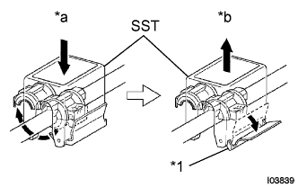
  1. I003839E07
    Install SST onto the piping clamp.
    *1
    Release Lever
    *a
    Push
    *b
    Pull
    SST
    09870-00015  

    HINT:
    Check the directions of the piping clamp and SST by referring to the illustration on the caution label.

  1. Push down SST and release the clamp lock.

    NOTICE:
    Do not deform the tube when pushing SST.

  1. Pull SST slightly, push the release lever, and then remove the piping clamp with SST.

  1. Disconnect the suction pipe.

    NOTICE:
    1. Do not use any tools when disconnecting the pipe.
    2. Seal the openings of the disconnected parts using vinyl tape to prevent moisture and foreign matter from entering.


6. DISCONNECT COOLER REFRIGERANT LIQUID PIPE A
SST
09870-00025  

HINT:
Disconnection procedure of the liquid pipe is the same as for the suction pipe.


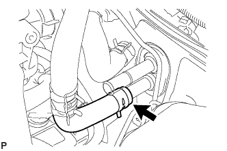
7. DISCONNECT HEATER WATER HOSE INLET

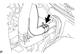
I102426
  1. Using pliers, grip the claw of the clip, slide the clip and disconnect the heater water inlet hose from the heater unit.


8. DISCONNECT HEATER WATER OUTLET HOSE A (FROM HEATER UNIT)

I102428
  1. Using pliers, grip the claw of the clip, slide the clip and disconnect the heater water outlet hose from the heater unit.


9. REMOVE INSTRUMENT PANEL SUB-ASSEMBLY (for LHD)
(Click here)

10. REMOVE INSTRUMENT PANEL SUB-ASSEMBLY (for RHD)
(Click here)

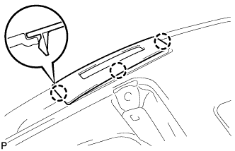
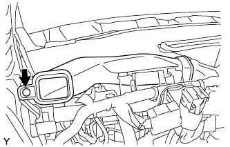
11. REMOVE INSTRUMENT PANEL FINISH PANEL END LH (for LHD)

  1. B133889
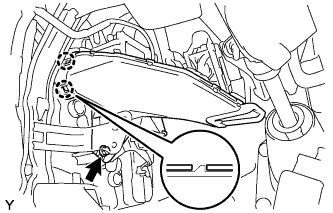
    Disengage the 3 claws and remove the instrument panel finish panel end.


12. REMOVE NO. 1 HEATER TO REGISTER DUCT

  1. I105921
    Remove the clip and the heater to register duct.


13. REMOVE NO. 2 HEATER TO REGISTER DUCT (for LHD)

  1. I102431
    Remove the screw and the heater to register duct.


14. REMOVE NO. 2 HEATER TO REGISTER DUCT (for RHD)

  1. I105839
    Remove the clip and the heater to register duct.


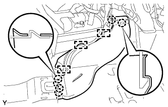
15. REMOVE REAR NO. 1 AIR DUCT
  1. Peel back the front floor mat enough to allow removal and installation of the air duct.

  1. I105890
    Disengage the 6 claws and 3 clamps and remove the rear air duct.


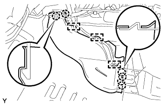
16. REMOVE REAR NO. 2 AIR DUCT
  1. Peel back the front floor mat enough to allow removal and installation of the air duct.

  1. I105891
    Disengage the 6 claws and 3 clamps and remove the rear air duct.


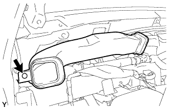
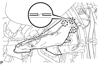
17. REMOVE NO. 1 AIR DUCT (for LHD)

  1. I102434
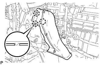
    Disengage the 3 claws and remove the air duct.


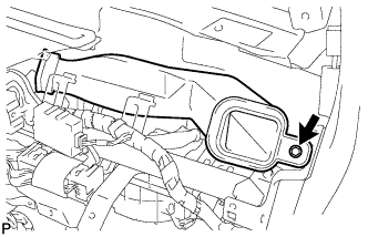
18. REMOVE NO. 1 AIR DUCT (for RHD)

  1. I105841
    Remove the screw.

  1. Disengage the 2 claws and remove the air duct.


19. REMOVE NO. 2 AIR DUCT

  1. I102435
    Disengage the 3 claws and remove the air duct.


20. REMOVE NO. 1 INSTRUMENT PANEL BRACE MOUNTING BRACKET

  1. I102436
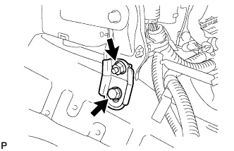
    Remove the bolt, nut and the instrument panel brace mounting bracket.

    HINT:
    Use the same procedure for both sides.


21. REMOVE ECM

  1. A226613
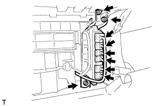
    Disconnect the 6 connectors.

  1. Remove the 3 nuts and ECM.


22. REMOVE STEERING COLUMN ASSEMBLY
(Click here)

23. REMOVE INSTRUMENT PANEL SIDE BRACKET (for LHD)

  1. I102438
    Remove the bolt and the instrument panel side bracket.


24. SEPARATE MAIN BODY ECU (for LHD)

  1. I102439
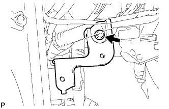
    Remove the 2 nuts and separate the main body ECU.


25. REMOVE MAIN BODY ECU (for RHD)

  1. E218716
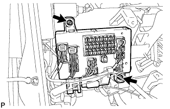
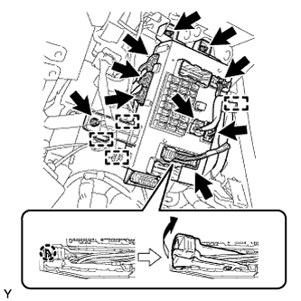
    Disconnect the connectors.

  1. Disengage the clamps.

  1. Remove the 3 nuts and separate the main body ECU.


26. REMOVE COOLER UNIT DRAIN HOSE

  1. I102468
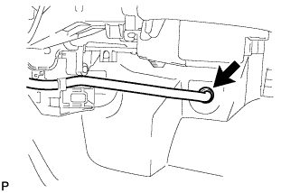
    Disconnect the cooler unit drain hose.


27. REMOVE INSTRUMENT PANEL REINFORCEMENT ASSEMBLY (for LHD)

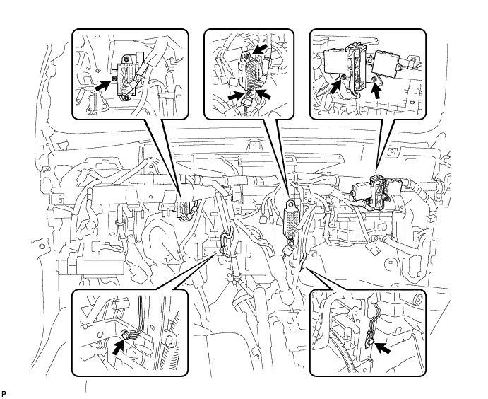
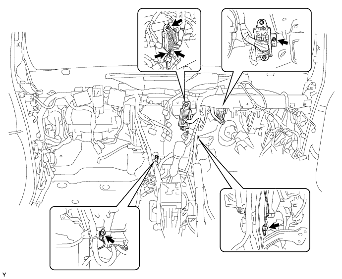
  1. Remove the 3 bolts and 5 nuts and disconnect the wire harness.

    I102440

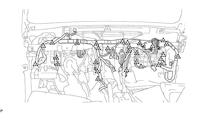
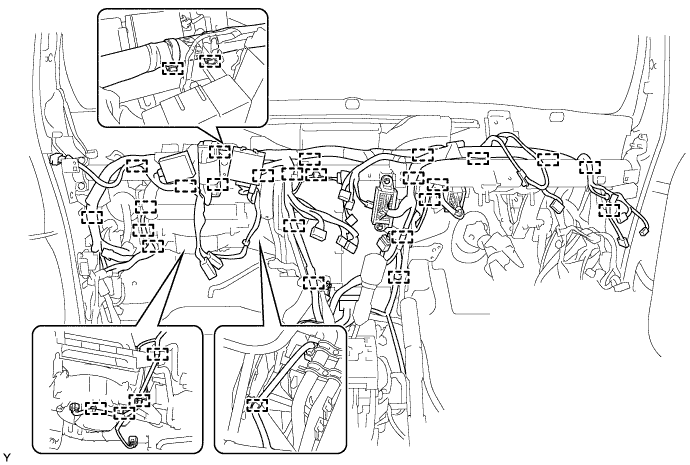
  1. Disconnect the connectors.

  1. Disengage the clamps.

    I102441

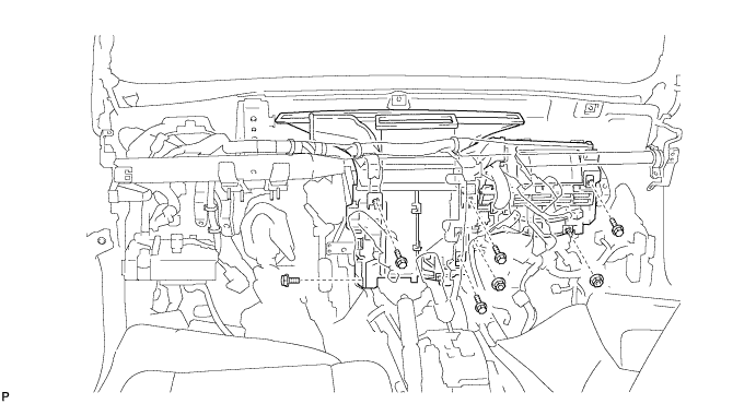
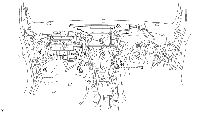
  1. Remove the 5 bolts and the 2 nuts.

    I102442

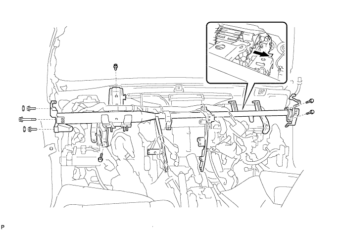
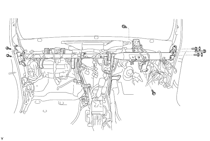
  1. Remove the 2 caps and the 7 bolts.

    I102443

  1. Disengage the reinforcement hook of the air conditioning unit, and remove the reinforcement.

  1. Remove the air conditioning unit.


28. REMOVE INSTRUMENT PANEL REINFORCEMENT ASSEMBLY (for RHD)

  1. Remove the bolts and nuts and disconnect the ground wire and junction connector.

    I105844

  1. Disengage the clamps.

    I105845

  1. Remove the 5 bolts and 2 nuts.

    I105846

  1. Remove 2 caps and 7 bolts.

    I105847

  1. Disengage the reinforcement hook of the air conditioning unit, and remove the reinforcement.

  1. Remove the air conditioning unit.


29. REMOVE AIR CONDITIONING UNIT ASSEMBLY

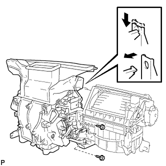
  1. I102445
    Remove the 2 screws.

  1. Remove the air conditioning unit as shown in the illustration.


30. REMOVE HEATER TO REGISTER DUCT ASSEMBLY

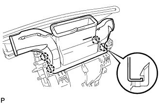
  1. I102449
    Disengage the 4 claws and remove the heater to register duct.


31. REMOVE LOWER DEFROSTER NOZZLE ASSEMBLY

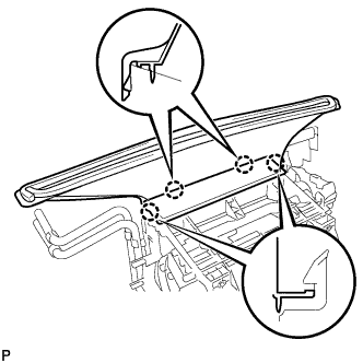
  1. I102450
    Disengage the 4 claws and remove the lower defroster nozzle.

← REMOVAL (Aug 2009 – Oct 2010)REMOVAL (Aug 2012 – Jul 2013) →