P0818 Driveline Disconnect Switch Input Circuit
Diagnostic trouble codes · Vehicles built Jul 2007 – Jul 2009
Versions by build date: Jul 2007 – Jul 2009 Aug 2009 – Oct 2010 Nov 2010 – Jul 2012 from Aug 2012
DESCRIPTION
The ECM detects the signal from the No. 2 transfer indicator switch (Transfer neutral position switch).This DTC indicates that the No. 2 transfer indicator switch remains ON.
| DTC No. |
DTC Detection Condition |
Trouble Area |
| P0818 |
No. 2 transfer indicator switch remains ON while vehicle is running under following conditions for 30 seconds. (2 trip detection logic):
|
|
MONITOR DESCRIPTION
The ECM detects whether or not the transfer high and low shift lever is in neutral by monitoring the signal from the No. 2 transfer indicator switch.If the ECM detects that the transfer high and low shift lever is in neutral under the following conditions, the ECM will conclude that there is a malfunction of the No. 2 transfer indicator switch:
- No. 2 transfer indicator switch indicates that the transfer high and low shift lever is in neutral.
- Transfer high and low shift lever is in the H position.
- The vehicle is traveling at 25.1 km/h (15.6 mph) or more.
- The No. 2 transfer indicator switch has been ON for more than 30 seconds.
WIRING DIAGRAM
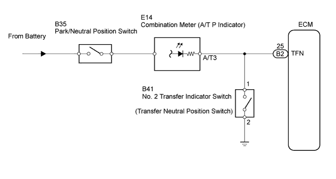

INSPECTION PROCEDURE
| 1. CHECK HARNESS AND CONNECTOR (NO. 2 TRANSFER INDICATOR SWITCH - BODY GROUND) |

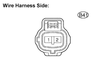 |
Disconnect the B2 connector of the ECM.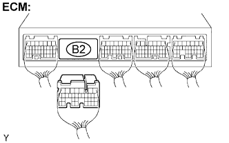
Disconnect the No. 2 transfer indicator switch connector.
Measure the resistance.
- Standard resistance:
Transfer Connection
Specified Condition
1 - Body ground
10 kΩ or higher
|
|
||||

| OK | |
 |
| 2. INSPECT NO. 2 TRANSFER INDICATOR SWITCH (TRANSFER NEUTRAL POSITION SWITCH) |
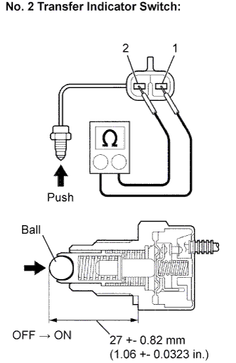 |
Remove the No. 2 transfer indicator switch.
Measure the resistance of the switch when pushing the ball at the tip of the switch.
- Standard resistance:
Tester Connection
Switch Condition
Specified Condition
1 - 2
Not pushed
10 kΩ or higher
1 - 2
Pushed
Below 1 Ω
|
|
||||

| OK | ||
 |
||
| ||
| 3. CHECK HARNESS AND CONNECTOR (COMBINATION METER - BODY GROUND) |
Disconnect the E14 connector of the combination meter.
Measure the resistance of the wire harness side connector.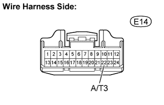
- Standard resistance:
Transfer Connection
Specified Condition
22 (A/T3) - Body ground
10 kΩ or higher
|
|
||||
| OK | ||
|
||
| ||