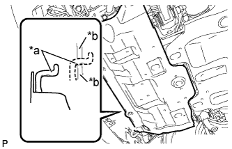
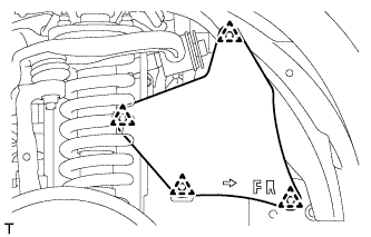
Unhook the engine under cover from the frame as shown in the illustration.
Text in Illustration
*a
Hook
*b
Frame
2.
DRAIN ENGINE COOLANT
CAUTION:
Do not remove the radiator cap sub-assembly while the engine and radiator assembly are still hot. Pressurized, hot engine coolant and steam may be released and cause serious burns.
Remove the service hole cover from the engine under cover.
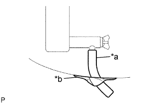
Install a vinyl hose to the radiator drain cock on the radiator assembly side.
Text in Illustration
*a
Vinyl Hose
*b
Tape
Fix the vinyl hose with tape.
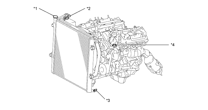
Text in Illustration
*1
Radiator Cap Sub-assembly
*2
Radiator Reserve Tank Cap Sub-assembly
*3
Radiator Drain Cock Plug
*4
Cylinder Block Drain Cock Plug
Loosen the radiator drain cock plug.
Remove the radiator cap sub-assembly and drain the engine coolant.
HINT:
Collect the engine coolant in a container and dispose of it according to the regulations in your area.
Loosen the cylinder block drain cock plug and drain the engine coolant from the engine.
NOTICE:
If engine coolant is not drained from the radiator drain cock plug, cylinder block drain cock plug and radiator reservoir, clogging in the radiator assembly or engine coolant leakage from the seal of water pump may result.
3.
REMOVE V-BANK COVER
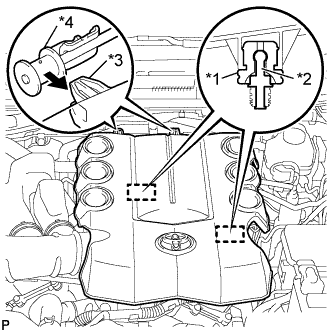
Raise the front of the V-bank cover to disengage the 2 cushions of the V-bank cover from the 2 pins.
Text in Illustration
*1
Cushion
*2
Pin
*3
Hook
*4
No. 1 V-bank Cover Bracket
Disengage the 2 hooks to remove the V-bank cover from the No. 1 V-bank cover bracket.
4.
REMOVE UPPER RADIATOR SUPPORT SEAL
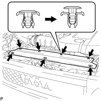
Disengage the 7 clips to remove the upper radiator support seal from the fan shroud.
5.
REMOVE FAN SHROUD
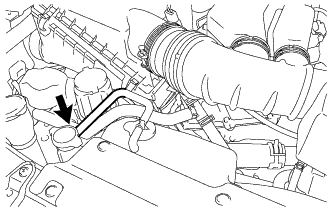
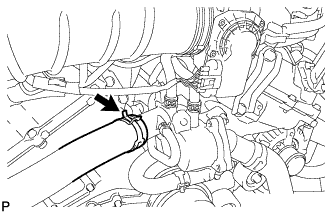
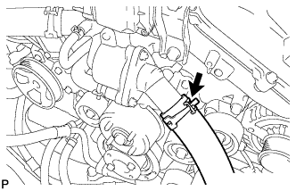
Disconnect the radiator reserve tank hose from the radiator assembly.
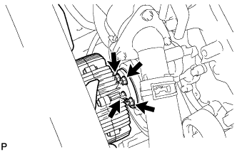
Loosen the 4 nuts holding the fan and fluid coupling assembly.
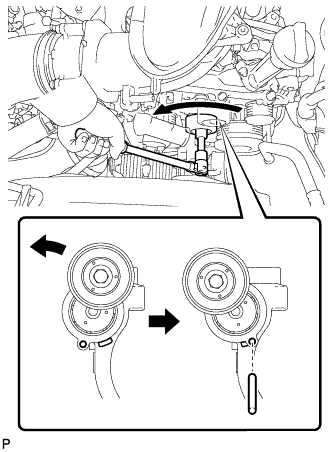
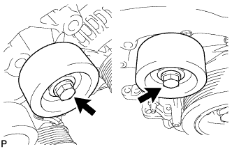
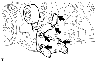
While turning the V-ribbed belt tensioner assembly counterclockwise, align the service hole for the V-ribbed belt tensioner assembly and the V-ribbed belt tensioner assembly fixing position, and then insert a bar of φ 6 mm (0.236 in.) into the service hole to fix the V-ribbed belt tensioner assembly in place.
HINT:
The pulley bolt for the V-ribbed belt tensioner assembly has a left-hand thread.
Remove the fan and generator V belt.
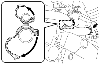
Disengage the clamp to separate the 2 oil cooler hoses from the hose clamp.
Text in Illustration
*1
Oil Cooler Hose
Remove the bolt to separate the radiator reserve tank assembly from the radiator assembly.
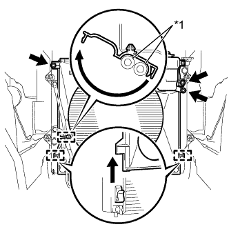
Remove the 2 bolts to separate the fan shroud from the radiator assembly.
Disengage the 2 guides of the fan shroud from the radiator assembly as shown in the illustration.
Remove the 4 nuts of the fan and fluid coupling assembly, and then remove the fan shroud together with the fan and fluid coupling assembly.
NOTICE:
Be careful not to damage the radiator core.
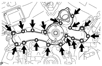
Remove the fan pulley from the engine water pump assembly.
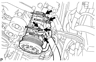
It is not necessary to completely remove the compressor. With the hoses connected to the compressor, hang the compressor on the vehicle body with a rope.
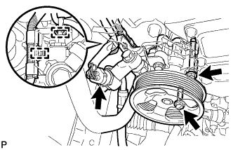
Disconnect the cooler compressor connector.
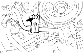
Remove the bolt and separate the suction hose.
Remove the 3 bolts and nut.
Using a E8 "TORX" socket wrench, remove the stud bolt and separate the cooler compressor assembly.