ADJUSTMENT
Removal / installation · Vehicles built Jul 2007 – Oct 2010
Versions by build date: Jul 2007 – Oct 2010 Nov 2010 – Jul 2012 Aug 2012 – Oct 2012 from Nov 2012
- NOTICE:
- For vehicles equipped with VSC, if the wheel alignment has been adjusted, and if suspension or underbody components have been removed/installed or replaced, be sure to perform the following initialization procedure in order for the system to function normally:
- Disconnect the negative battery terminal for more than 2 seconds.
- Reconnect the negative battery terminal.
- Perform zero point calibration of the yaw rate and deceleration sensor and test mode inspection.
- HINT:
- (Click here)
| 1. INSPECT TIRES |

Check the tires for wear and proper inflation pressure.
- Cold tire inflation pressure:
Tire Size
Front Wheel
kPa (kgf/cm2, psi)
Rear Wheel
kPa (kgf/cm2, psi)
265/75R16 116S
220 (2.2, 32)
220 (2.2, 32)
Using a dial indicator, check the tire runout.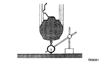

- Tire runout:
- 3.0 mm (0.118 in.) or less
| 2. MEASURE VEHICLE HEIGHT |
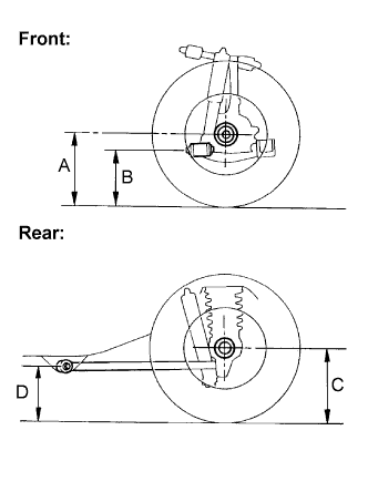 |
| Vehicle Model |
A-B |
C-D |
| GSJ15L-GKFSKY |
87.3 mm (3.44 in.) |
61.5 mm (2.42 in.) |
| GSJ15L-GKASKY |
87.3 mm (3.44 in.) |
61.6 mm (2.43 in.) |
| GSJ15L-GKASKV |
87.3 mm (3.44 in.) |
61.6 mm (2.43 in.) |
| GSJ15L-GKASKC |
87.2 mm (3.43 in.) |
61.4 mm (2.42 in.) |
- Measuring points:
- A:
- Ground clearance of front wheel center
- B:
- Ground clearance of adjustment cam bolt center
- C:
- Ground clearance of rear wheel center
- D:
- Ground clearance of lower control arm set bolt center
- NOTICE:
- Before inspecting the wheel alignment, check the vehicle height.
| 3. INSPECT WHEEL TURNING ANGLE |
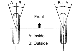 |
Turn the steering wheel fully, and measure the wheel turning angle.
- Wheel turning angle (unloaded vehicle):
Inside wheel
Outside wheel
(Reference)
33°10' (31°10' to 34°10')
33.16° (31.16° to 34.16°)
29°38'
(29.63°)
| 4. INSPECT CAMBER, CASTER AND STEERING AXIS INCLINATION |
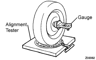 |
Install the camber-caster-kingpin gauge and position the front wheel on the wheel alignment tester.
Inspect the camber, caster and steering axis inclination.
- Camber, caster and steering axis inclination (unloaded vehicle):
Camber
Caster
Steering Axis Inclination
-0°22' to 0°38'
(-0.36°to 0.64°)
2°47' to 3°47'
(2.79°to 3.79°)
11°51' to 12°51'
(11.85°to 12.85°)
- NOTICE:
- Perform the inspection while the vehicle is empty (without spare tires or tools on board).
- The tolerance for the difference between the left and right wheels is 30' (0.50°) or less for both the camber and caster.
- Perform the inspection while the vehicle is empty (without spare tires or tools on board).
| 5. ADJUST CAMBER AND CASTER |
- NOTICE:
- Inspect the toe-in after the camber has been adjusted.
Loosen the nut and bolt.
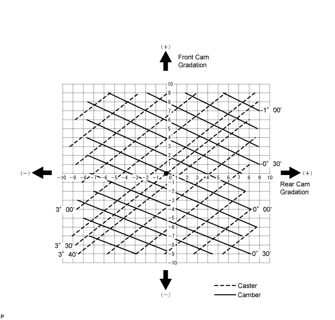
Turn camber adjust cam No. 2 and the toe adjust cam and adjust the camber and the caster.
- HINT:
- Try to adjust the camber and caster to the central values.
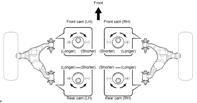
How to read the adjustment chart (using examples).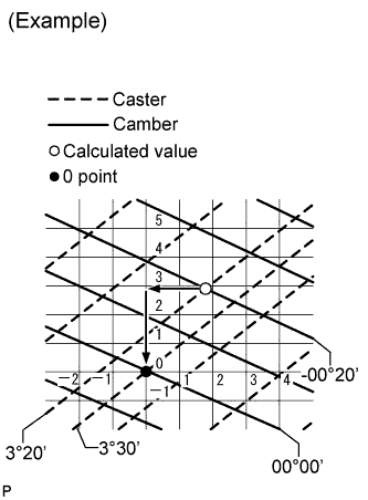
Measure the present alignment.
- Camber:
- 0°20' (0.33°)
- Caster:
- 3°20' (3.33°)
Calculate the difference between the standard value (A) and the measured value (B) on the adjustment chart.
- Standard value:
- Camber:
- 0°00' (0°)
- Caster:
- 3°30' (3.5°)
- Formula:
- B - A = C
- Camber:
- 0°00' - (0°20') = -0°20'
- Caster:
- 3°20' - (3°30') = -0°10'
As shown in the chart, read the distance from the marked point to 0 point, and adjust the front and/or rear adjusting cams accordingly.
- Toe adjust cam:
- - (Shorter) 2.8
- Camber adjust cam:
- - (Shorter) 1.8
| 6. INSPECT TOE-IN |
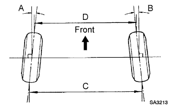 |
- Toe-in:
A+B
C-D
-0°05' to 0°15'
(-0.08° to 0.24°)
-1.0 to 3.0 mm
(-0.04 to 0.12 in.)
| 7. ADJUST TOE-IN |
Remove the rack boot set clips.
Loosen the tie rod end lock nuts.
Turn the right and left rack ends uniformly to adjust the toe-in.
- HINT:
- Try to adjust the toe-in to the middle of the specified range.
Make sure that the lengths of the right and left rack ends are the same.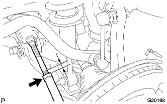
Tighten the tie rod end lock nuts.
- Torque:
- 88 N*m{ 897 kgf*cm , 65 ft.*lbf }
Place the boots on the seats and install the clips.
- HINT:
- Make sure that the boots are not twisted.
| 8. FRONT WHEELS FACING STRAIGHT AHEAD |
| 9. DISCONNECT CABLE FROM NEGATIVE BATTERY TERMINAL (w/ VSC) |
- NOTICE:
- Disconnect the negative battery terminal for more than 2 seconds.
| 10. CONNECT CABLE TO NEGATIVE BATTERY TERMINAL (w/ VSC) |
| 11. PERFORM YAW RATE SENSOR ZERO POINT CALIBRATION (w/ VSC) |
| 12. CHECK STEERING ANGLE SENSOR ZERO POINT CALIBRATION (w/ VSC) |