ADJUSTMENT
Removal / installation · Vehicles built from Nov 2012
Versions by build date: Jul 2007 – Oct 2010 Nov 2010 – Jul 2012 Aug 2012 – Oct 2012 from Nov 2012
- NOTICE:
- For vehicles equipped with VSC, if the wheel alignment has been adjusted, and if suspension or underbody components have been removed/installed or replaced, be sure to perform the following initialization procedure in order for the system to function normally:
- Perform zero point calibration of the yaw rate and deceleration sensor and test mode inspection.
| 1. INSPECT TIRES |

Check the tires for wear and proper inflation pressure.
- Cold Tire Inflation Pressure:
Tire Size
Front Wheel
kPa (kgf/cm2, psi)
Rear Wheel
kPa (kgf/cm2, psi)
265/70R17 115S
220 (2.2, 32)
220 (2.2, 32)
Using a dial indicator, check the tire runout.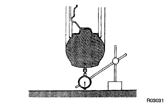

- Tire runout:
- 3.0 mm (0.118 in.) or less
| 2. MEASURE VEHICLE HEIGHT |
- NOTICE:
- Before inspecting the wheel alignment, check the vehicle height.
- Be sure to perform measurement on a level surface.
- If it is necessary to go under the vehicle for measurement, confirm that the parking brake is applied and the vehicle is secured with chocks.
- Inspect while the vehicle is unloaded.
- The standard value shown here is a value that is used for adjusting the wheel alignment and does not indicate the height of an actual vehicle.
- Before inspecting the wheel alignment, check the vehicle height.
Bounce the vehicle up and down at the corners to stabilize the suspension before inspecting the vehicle height.
Measure the vehicle height.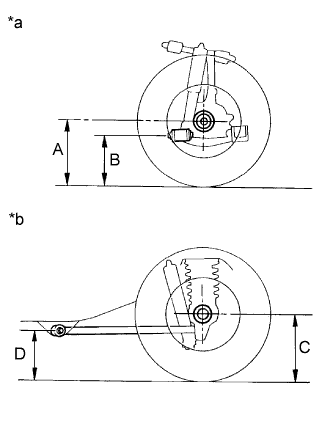
Text in Illustration *a
Front Side
*b
Rear Side
- Measuring points:
- A:
- Ground clearance of front wheel center
- B:
- Ground clearance of adjustment cam bolt center
- C:
- Ground clearance of rear wheel center
- D:
- Ground clearance of lower control arm set bolt center
- Standard Vehicle Height (Unloaded Vehicle):
Vehicle Model
A - B
C - D
GSJ15L-GKFSKY
88.4 mm (3.48 in.)
61.6 mm (2.43 in.)
GSJ15L-GKFSKY
(for Double Tank Type)
85.9 mm (3.38 in.)
62.4 mm (2.46 in.)
GSJ15L-GKASKY
87.7 mm (3.45 in.)
61.9 mm (2.44 in.)
GSJ15L-GKASKY
(for Double Tank Type)
85.5 mm (3.37 in.)
62.5 mm (2.46 in.)
GSJ15L-GKASKV
87.7 mm (3.45 in.)
61.9 mm (2.44 in.)
GSJ15L-GKASKV
(for Double Tank Type)
85.1 mm (3.35 in.)
62.5 mm (2.46 in.)
GSJ15L-GKFSKV
86.8 mm (3.42 in.)
62.1 mm (2.44 in.)
GSJ15L-GKFSKV
(for Double Tank Type)
84.3 mm (3.32 in.)
62.8 mm (2.47 in.)
GSJ15L-GKASKC
87.6 mm (3.45 in.)
62.6 mm (2.46 in.)
GSJ15R-GKASKN
88.8 mm (3.50 in.)
58.8 mm (2.31 in.)
GSJ15R-GKASKN
(for Double Tank Type)
86.6 mm (3.41 in.)
60.0 mm (2.36 in.)
GSJ15R-GKASKQ
87.1 mm (3.43 in.)
60.3 mm (2.37 in.)
GSJ15R-GKASKQ
(for Double Tank Type)
85.2 mm (3.35 in.)
61.7 mm (2.43 in.)
GSJ15R-GKASKY
87.6 mm (3.45 in.)
58.7 mm (2.31 in.)
GSJ15R-GKASKY
(for Double Tank Type)
85.4 mm (3.36 in.)
59.9 mm (2.36 in.)
| 3. INSPECT CAMBER, CASTER AND STEERING AXIS INCLINATION |
Install the camber-caster-kingpin gauge and position the front wheel on the wheel alignment tester.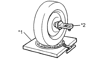
Text in Illustration *1
Wheel Alignment Tester
*2
Camber-caster-kingpin Gauge
Inspect the camber, caster and steering axis inclination.
- Camber, Caster and Steering Axis Inclination (Unloaded Vehicle):
Vehicle Model
Camber
Caster
Steering Axis Inclination
GSJ15L-GKFSKY
0°07' +/- 30'
(0.12° +/- 0.50°)
3°19' +/- 30'
(3.32° +/- 0.50°)
12°23' +/- 30'
(12.38° +/- 0.50°)
GSJ15L-GKFSKY
(for Double Tank Type)
0°10' +/ -30'
(0.17° +/- 0.50°)
3°15' +/- 30'
(3.25° +/- 0.50°)
12°20' +/- 30'
(12.33° +/- 0.50°)
GSJ15L-GKASKY
0°08 '+/- 30'
(0.13° +/- 0.50°)
3°18' +/- 30'
(3.30° +/- 0.50°)
12°22' +/- 30'
(12.36° +/- 0.50°)
GSJ15L-GKASKY
(for Double Tank Type)
0°10' +/- 30'
(0.17° +/- 0.50°)
3°14' +/- 30'
(3.24° +/- 0.50°)
12°19' +/- 30'
(12.32° +/ -0.50°)
GSJ15L-GKASKV
0°08' +/- 30'
(0.13° +/- 0.50°)
3°18' +/- 30'
(3.30° +/- 0.50°)
12°22' +/- 30'
(12.36° +/- 0.50°)
GSJ15L-GKASKV
(for Double Tank Type)
0°11' +/- 30'
(0.18° +/- 0.50°)
3°14' +/- 30'
(3.23° +/- 0.50°)
12°19' +/- 30'
(12.31° +/- 0.50°)
GSJ15L-GKFSKV
0°09' +/- 30'
(0.15° +/- 0.50°)
3°17' +/- 30'
(3.28° +/- 0.50°)
12°21' +/- 30'
(12.35° +/- 0.50°)
GSJ15L-GKFSKV
(for Double Tank Type)
0°12' +/- 30'
(0.20° +/- 0.50°)
3°12' +/- 30'
(3.20° +/- 0.50°)
12°18' +/- 30'
(12.30° +/- 0.50°)
GSJ15L-GKASKC
0°08' +/ -30'
(0.13° +/- 0.50°)
3°18' +/- 30'
(3.30° +/- 0.50°)
12°22' +/- 30'
(12.36° +/- 0.50°)
GSJ15R-GKASKN
0°07' +/- 30'
(0.12° +/- 0.50°)
3°19' +/- 30'
(3.32° +/- 0.50°)
12°23' +/- 30'
(12.38° +/- 0.50°)
GSJ15R-GKASKN
(for Double Tank Type)
0°10' +/- 30'
(0.16° +/- 0.50°)
3°16' +/- 30'
(3.26° +/- 0.50°)
12°20' +/- 30'
(12.34° +/- 0.50°)
GSJ15R-GKASKQ
0°09' +/- 30'
(0.15° +/- 0.50°)
3°17' +/- 30'
(3.28° +/- 0.50°)
12°21' +/- 30'
(12.35° +/- 0.50°)
GSJ15R-GKASKQ
(for Double Tank Type)
0°11' +/- 30'
(0.18° +/- 0.50°)
3°14' +/- 30'
(3.23° +/- 0.50°)
12°19' +/- 30'
(12.31° +/- 0.50°)
GSJ15R-GKASKY
0°09' +/- 30'
(0.14° +/- 0.50°)
3°17' +/- 30'
(3.29° +/- 0.50°)
12°21' +/- 30'
(12.35° +/- 0.50°)
GSJ15R-GKASKY
(for Double Tank Type)
0°11' +/- 30'
(0.18° +/- 0.50°)
3°14' +/- 30'
(3.23° +/- 0.50°)
12°19' +/- 30'
(12.31° +/- 0.50°)
- NOTICE:
- Inspect while the vehicle is unloaded.
- The tolerance for the difference between the left and right wheels is 30' (0.50°) or less for both the camber and caster.
- Inspect while the vehicle is unloaded.
| 4. ADJUST CAMBER AND CASTER |
- HINT:
- Inspect the toe-in after the camber has been adjusted.
Loosen the nut and bolt.
Turn the front cam and the rear cam and adjust the camber and the caster.
- HINT:
- Try to adjust the camber and caster to the central values.
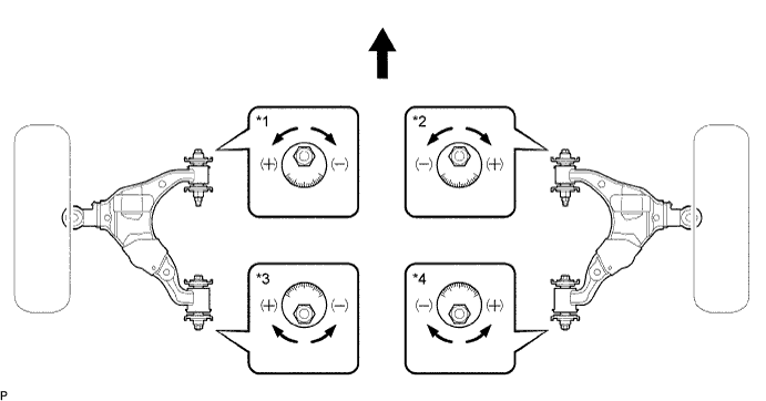
Text in Illustration *1
Front Cam LH
*2
Front Cam RH
*3
Rear Cam LH
*4
Rear Cam RH

Front of the Vehicle
-
-
Read the adjustment chart (example).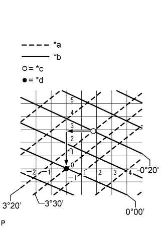
Text in Illustration *a
Caster
*b
Camber
*c
Measured Value
*d
Standard Value
Find the wheel alignment standard value applicable for the particular model.
Mark the selected standard value on the adjustment chart.
- Standard Value (Reference):
Camber
Caster
0°00' (0.00°)
3°30' (3.50°)
Mark the alignment value measured when the vehicle is unloaded on the adjustment chart.
- Measured Value (Reference):
Camber
Caster
-0°20' (-0.33°)
3°20' (3.33°)
As shown in the chart, read the distance from the marked point to 0, and adjust the front and/ or rear cams accordingly.
- Amount to Turn Adjusting Cams (by Gradation):
Front Cam
Rear Cam
+3
+2
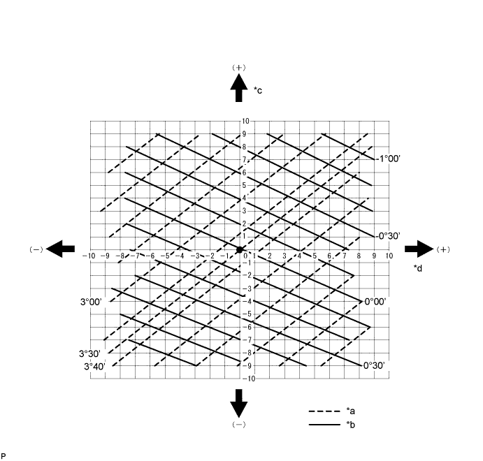
Text in Illustration *a
Caster
*b
Camber
*c
Front Cam Gradation
*d
Rear Cam Gradation
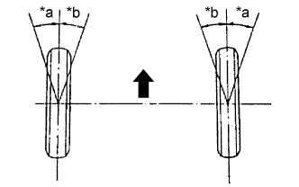
| 5. INSPECT TOE-IN |
Bounce the vehicle up and down at the corners to stabilize the suspension and inspect the toe-in.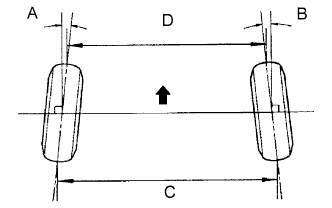
Front of the Vehicle
- Toe-in (Unloaded Vehicle):
A + B
C - D
0°05' +/- 10'
(0.08° +/- 0.17°)
1.0 +/- 2.0 mm
(0.04 +/- 0.08 in.)
- NOTICE:
- Measure "C - D" only when "A + B" cannot be measured.
| 6. ADJUST TOE-IN |
Remove the rack boot set clips.
Loosen the tie rod end lock nuts.
Turn the right and left rack ends uniformly to adjust the toe-in.
- HINT:
- Try to adjust the toe-in to the middle of the specified range.
Make sure that the lengths of the right and left rack ends are the same.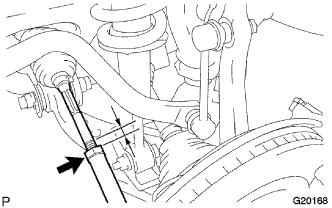
Tighten the tie rod end lock nuts.
- Torque:
- 88 N*m{ 897 kgf*cm , 65 ft.*lbf }
Place the boots on the seats and install the rack boot set clips.
- HINT:
- Make sure that the boots are not twisted.
| 7. INSPECT WHEEL TURNING ANGLE |
 |
Turn the steering wheel fully, and measure the wheel turning angle.
Text in Illustration *a
Inside
*b
Outside
Front of the Vehicle
- Wheel Turning Angle (Unloaded Vehicle):
Vehicle Model
Inside Wheel
Outside Wheel
(Reference)
GSJ15L-GKFSKY
33° 9' (31° 9' to 34° 9')
33.15° (31.15° to 34.15°)
29°36'
(29.60°)
GSJ15L-GKFSKY
(for Double Tank Type)
33°11' (31°11' to 34°11')
33.18° (31.18° to 34.18°)
29°39'
(29.66°)
GSJ15L-GKASKY
33°10' (31°10' to 34°10')
33.16° (31.16° to 34.16°)
29°37'
(29.62°)
GSJ15L-GKASKY
(for Double Tank Type)
33°11' (31°11' to 34°11')
33.18° (31.18° to 34.18°)
29°40'
(29.67°)
GSJ15L-GKASKV
33°10' (31°10' to 34°10')
33.16° (31.16° to 34.16°)
29°37'
(29.62°)
GSJ15L-GKASKV
(for Double Tank Type)
33°11' (31°11' to 34°11')
33.18° (31.18° to 34.18°)
29°40'
(29.67°)
GSJ15L-GKFSKV
33°10' (31°10' to 34°10')
33.17° (31.17° to 34.17°)
29°38'
(29.64°)
GSJ15L-GKFSKV
(for Double Tank Type)
33°12' (31°12' to 34°12')
33.20° (31.20° to 34.20°)
29°41'
(29.69°)
GSJ15L-GKASKC
33°10' (31°10' to 34°10')
33.16° (31.16° to 34.16°)
29°37'
(29.62°)
GSJ15R-GKASKN
33°9' (31° 9' to 34° 9')
33.15° (31.15° to 34.15°)
29°36'
(29.60°)
GSJ15R-GKASKN
(for Double Tank Type)
33°10' (31°10' to 34°10')
33.17° (31.17° to 34.17°)
29°39'
(29.65°)
GSJ15R-GKASKQ
33°10' (31°10' to 34°10')
33.17° (31.17° to 34.17°)
29°38'
(29.64°)
GSJ15R-GKASKQ
(for Double Tank Type)
33°11' (31°11' to 34°11')
33.19° (31.19° to 34.19°)
29°40'
(29.67°)
GSJ15R-GKASKY
33°10' (31°10' to 34°10')
33.16° (31.16° to 34.16°)
29°38'
(29.63°)
GSJ15R-GKASKY
(for Double Tank Type)
33°11' (31°11' to 34°11')
33.19° (31.19° to 34.19°)
29°40'
(29.67°)
| 8. PLACE FRONT WHEELS FACING STRAIGHT AHEAD |
| 9. PERFORM YAW RATE SENSOR ZERO POINT CALIBRATION (w/ VSC) |