Refer to the procedures up to "REMOVE CHAIN SUB-ASSEMBLY" (Click here).
3.
REMOVE NO. 1 COOL AIR INLET
Remove the 2 bolts and the No. 1 cool air inlet.
4.
REMOVE EXHAUST PIPE STOPPER BRACKET (for 4WD)
5.
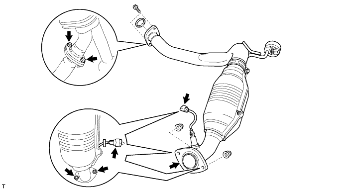
REMOVE NO. 2 FRONT EXHAUST PIPE ASSEMBLY
Disconnect the oxygen sensor connector.
Remove the 2 bolts and 2 nuts.
Disengage the support and remove the front exhaust pipe and 2 gaskets.
6.
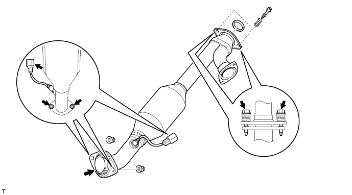
REMOVE FRONT EXHAUST PIPE ASSEMBLY
Disconnect the oxygen sensor connector.
Remove the 2 bolts, 2 springs and 2 nuts, then separate the front exhaust pipe from the exhaust manifold RH.
7.
REMOVE MANIFOLD STAY
Remove the 3 bolts and manifold stay.
8.
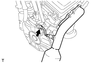
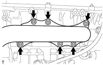
REMOVE EXHAUST MANIFOLD SUB-ASSEMBLY RH
Disconnect the air fuel ratio sensor connector.
Remove the 6 nuts and exhaust manifold.
Remove the gasket.
9.
DISCONNECT NO. 1 FUEL PIPE SUB-ASSEMBLY
Remove the No. 2 fuel pipe clamp.
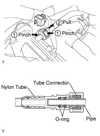
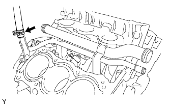
Pinch the tube connector, and then pull the fuel pipe out of the delivery pipe as shown in the illustration.
NOTICE:
Remove any dirt and foreign objects from the fuel tube connector before performing this work.
Do not allow any scratches or foreign objects on the parts when disconnecting, as the fuel tube connector has the O-ring that seals the pipe.
Perform this work by hand. Do not use any tools.
Do not forcibly bend, twist or turn the nylon tube.
Protect the disconnected part by covering it with a vinyl bag after disconnecting the fuel tube.
If the fuel tube connector and pipe are stuck, push and pull to release them.
10.
DISCONNECT NO. 2 FUEL PIPE SUB-ASSEMBLY
Remove the No. 2 fuel pipe clamp.
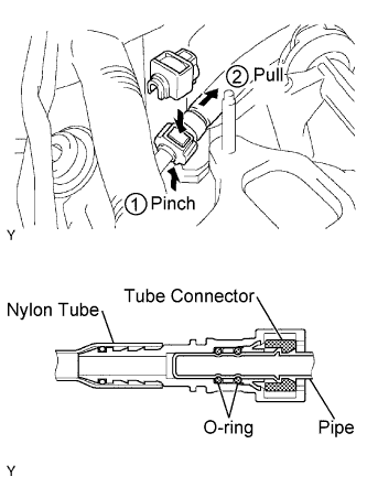
Pinch the tube connector, and then pull the fuel pipe out of the delivery pipe as shown in the illustration.
NOTICE:
Remove any dirt and foreign objects from the fuel tube connector before performing this work.
Do not allow any scratches or foreign objects on the parts when disconnecting, as the fuel tube connector has the O-ring that seals the pipe.
Perform this work by hand. Do not use any tools.
Do not forcibly bend, twist or turn the nylon tube.
Protect the disconnected part by covering it with a vinyl bag after disconnecting the fuel tube.
If the fuel tube connector and pipe are stuck, push and pull to release them.
11.
REMOVE INTAKE MANIFOLD
Disconnect the 6 fuel injector connectors.
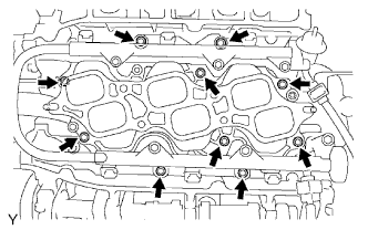
Remove the 10 bolts, then remove the intake manifold and gasket.
12.
REMOVE WATER BY-PASS JOINT REAR
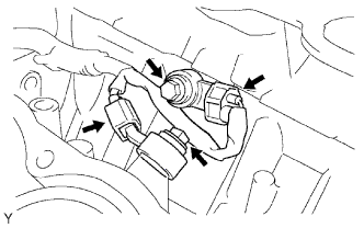
Disconnect the engine coolant temperature sensor connector.
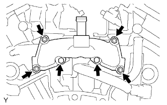
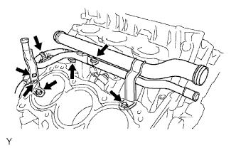
Remove the 2 bolts and 4 nuts, then remove the water by-pass joint RR and 2 gaskets.
Remove the O-ring from the water outlet hose.
13.
REMOVE CAMSHAFT TIMING GEARS AND NO. 2 CHAIN (for Bank 1)
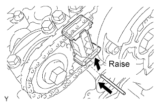
While raising the No. 2 chain tensioner, insert a pin of φ 1.0 mm (0.039 in.) into the hole to fix it.
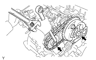
Hold the hexagonal portion of the camshaft with a wrench.
NOTICE:
Be careful not to damage the cylinder head and valve lifter with the wrench.
Remove the 2 bolts, then remove the camshaft timing gear, camshaft timing gear assembly and No. 2 timing chain.
NOTICE:
Do not disassemble the camshaft timing gear assembly.
14.
REMOVE NO. 2 CHAIN TENSIONER ASSEMBLY
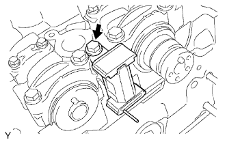
Remove the bolt, then remove the No. 2 chain tensioner.
15.
REMOVE CAMSHAFTS (for Bank 1)
NOTICE:
Keep the camshaft level while it is being removed. The camshaft thrust clearance is very small and failing to keep it level could crack or damage the cylinder head journal surface, which receives the thrust force. This could subsequently lead the camshaft to seize or break. Perform the following steps to avoid such problems.
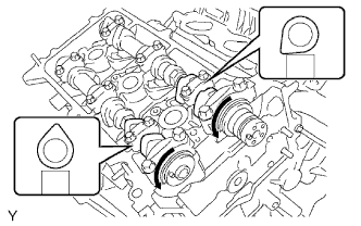
Rotate the camshafts counterclockwise using a wrench so that the cam lobes of No. 1 cylinder face in the directions shown in the illustration.
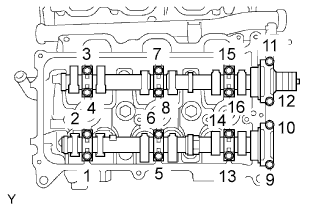
Using several steps, loosen and remove the 16 bearing cap bolts uniformly in the sequence shown in the illustration.
Remove the 8 bearing caps and 2 camshafts.
16.
REMOVE NO. 2 CAMSHAFT BEARING
17.
REMOVE CYLINDER HEAD SUB-ASSEMBLY
Remove the bolt and separate the ground cable.
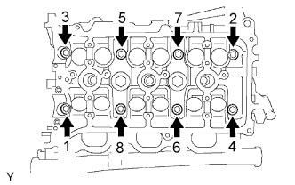
Using several steps, loosen the 8 cylinder head bolts on the cylinder head uniformly with a 10 mm bi-hexagon wrench in the sequence shown in the illustration. Remove the 8 cylinder head bolts and 8 plate washers.
NOTICE:
Be careful not to drop the plate washers into the cylinder head.
Cylinder head warpage or cracking could result from removing the bolts in the wrong order.
Lift the cylinder head from the dowels on the cylinder block, and place the cylinder head on wooden blocks on a bench.
NOTICE:
Be careful not to drop the plate washers into the cylinder head.
If the cylinder head is difficult to lift off, pry between the cylinder head and cylinder block with a screwdriver.
18.
REMOVE CYLINDER HEAD GASKET
19.
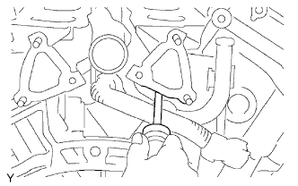
DISCONNECT HEATER WATER INLET HOSE
Disconnect the heater water inlet hose from the water outlet pipe.