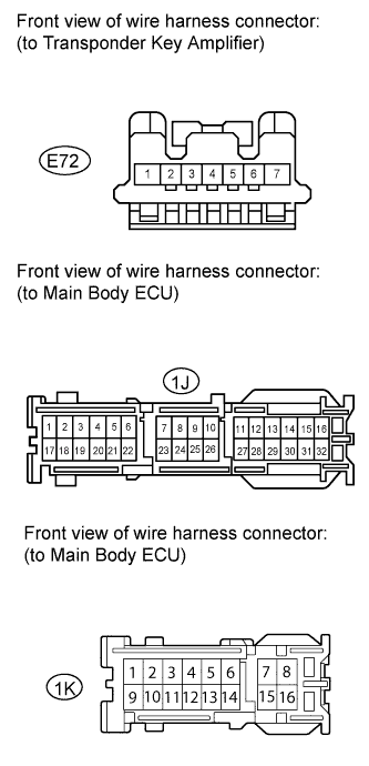
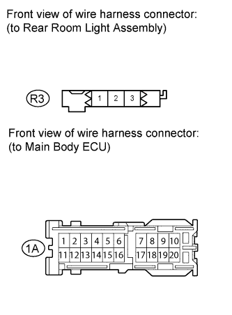
Illumination Circuit
Circuit diagnosis · Vehicles built Jul 2007 – Oct 2010
Versions by build date: Jul 2007 – Oct 2010 Nov 2010 – Jul 2012 Aug 2012 – Jul 2014 from Aug 2014
DESCRIPTION
- Upon receiving signals from the switches, the main body ECU illuminates the lights.
WIRING DIAGRAM
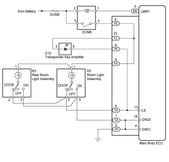

INSPECTION PROCEDURE
| 1. PERFORM ACTIVE TEST USING INTELLIGENT TESTER (ILLUMINATED ENTRY SYSTEM) |
 |
Connect the intelligent tester to DLC3.
Turn the ignition switch ON.
Turn the tester on.
Turn the room light switch DOOR position.
All doors closed (courtesy light switches OFF)
Enter the following menus: Body Electrical / Body / Active Test/ Illuminated Entry System.
Check the transponder key amplifier (Ignition key cylinder light) and room lights while operating the main body ECU using the tester.
- Body (Main Body ECU):
Tester Display
|
Test Part
|
Control Range
|
Normal Condition
|
Illuminated Entry System
|
Transponder key amplifier (Ignition key cylinder light) and room lights
|
ON/OFF
|
-
|
- OK:
- The illuminated entry system operates normally when operating it through the intelligent tester.
- Result:
Result
|
Proceed to
|
OK
|
A
|
NG (All lights do not come on)
|
B
|
NG (Transponder key amplifier (ignition key cylinder light ) does not come on)
|
C
|
NG (Room lights do not come on)
|
D
|
| A |
|
 |
|
| PROCEED TO NEXT CIRCUIT INSPECTION SHOWN IN PROBLEM SYMPTOMS TABLE (Click here)
|
|
| 2. INSPECT FUSE (DOME) |
|
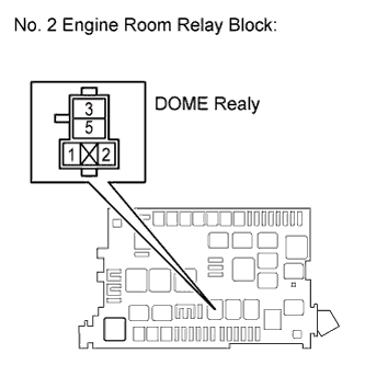
Remove the DOME fuse from the No. 2 engine room relay block.
Measure the resistance according value(s) in the table below.
- Standard resistance:
Tester Connection
|
Condition
|
Specified Condition
|
DOME fuse
|
Always
|
Below 1 Ω
|
Reinstall the DOME fuse.
|
NG |
 |
|
|
|
| OK |
|
 |
|
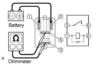
| 3. INSPECT RELAY (DOME) |
|
Remove the DOME relay from the No. 2 engine room relay block.
Measure the resistance according value(s) in the table below.
- Standard resistance:
Tester Connection
|
Condition
|
Specified Condition
|
3 - 5
|
Voltage is not applied between terminals 1 and 2
|
10 kΩ or higher
|
3 - 5
|
Apply the battery voltage between terminals 1 and 2
|
Below 1 Ω
|
Reinstall the DOME relay.
|
NG |
|
|
|
|
| OK |
|
|
|
| 4. CHECK HARNESS AND CONNECTOR (DOME FUSE - DOME RELAY) |
|
- Remove the DOME relay from the No. 2 engine room relay block.
Measure the voltage according value(s) in the table below.
- Standard voltage:
Tester Connection
|
Condition
|
Specified Condition
|
DOME relay terminal 2 - Body ground
|
Always
|
11 to 14 V
|
DOME relay terminal 5 - Body ground
|
Always
|
11 to 14 V
|
Reinstall the DOME relay.
|
NG |
|
|
| REPAIR OR REPLACE HARNESS OR CONNECTOR |
|
|
| OK |
|
|
|
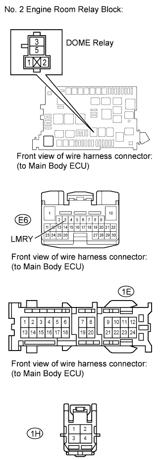
| 5. CHECK HARNESS AND CONNECTOR (MAIN BODY ECU - DOME RELAY, BODY GROUND) |
|
- Remove the DOME relay from the No. 2 engine room relay block.
Disconnect the E6 and 1E, 1H main body ECU connectors.
Measure the resistance according value(s) in the table below.
- Standard resistance:
Tester Connection
|
Condition
|
Specified Condition
|
E6-3 (LMRY) - DOME relay terminal 1
|
Always
|
Below 1 Ω
|
1E-6 - DOME relay terminal 3
|
Always
|
Below 1 Ω
|
1H-2 - Body ground
|
Always
|
Below 1 Ω
|
Reconnect the main body ECU connectors.
Reinstall the DOME relay.
|
NG |
|
|
| REPAIR OR REPLACE HARNESS OR CONNECTOR |
|
|
| OK |
|
|
|
|
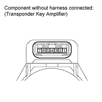
| 6. INSPECT TRANSPONDER KEY AMPLIFIER |
|
- Remove the transponder key amplifier.
Inspect the ignition key cylinder light.
Apply battery voltage to the terminals and check that the ignition key cylinder comes on.
- OK:
Measurement Connection
|
Specified Condition
|
Positive battery - 2
Negative battery - 6
|
Ignition key cylinder light comes on
|
Reinstall the transponder key amplifier.
|
NG |
|
|
|
|
| OK |
|
|
|
| 7. CHECK HARNESS AND CONNECTOR (TRANSPONDER KEY AMPLIFIER - MAIN BODY ECU) |
|
- Disconnect the E72 transponder key amplifier connector.
Disconnect the 1J and 1K main body ECU connectors.
Measure the resistance according value(s) in the table below.
- Standard resistance:
Tester Connection
|
Condition
|
Specified Condition
|
1J-22 - E72-2
|
Always
|
Below 1 Ω
|
1K-9 - E72-6
|
Always
|
Below 1 Ω
|
Reconnect the main body ECU connectors.
Reconnect the transponder key amplifier connector.
|
NG |
|
|
| REPAIR OR REPLACE HARNESS OR CONNECTOR |
|
|
| OK |
|
|
|
|
| 8. INSPECT ROOM LIGHT ASSEMBLY |
|
Inspect the room light assembly (Click here) and rear room light assembly (Click here).
- OK:
- Room lights assembly is normal.
- Result:
Result
|
Proceed to
|
OK
|
A
|
NG (Room light assembly)
|
B
|
NG (Rear room light assembly)
|
C
|
|
B |
|
|
|
|
|
C |
|
|
|
|
| A |
|
|
|
| 9. CHECK HARNESS AND CONNECTOR (MAIN BODY ECU - REAR ROOM LIGHT ASSEMBLY) |
|
Disconnect the R2 room light connector.
- Disconnect the R3 rear room light connector.
Disconnect the 1A main body ECU connector.
Measure the resistance according value(s) in the table below.
- Standard resistance:
Tester Connection
|
Condition
|
Specified Condition
|
R3-1 - 1A-9
|
Always
|
Below 1 Ω
|
R3-2 - 1A-8
|
Always
|
Below 1 Ω
|
R3-3 - 1A-7
|
Always
|
Below 1 Ω
|
Reconnect the main body ECU connector.
Reconnect the room light connectors.
|
NG |
|
|
| REPAIR OR REPLACE HARNESS OR CONNECTOR |
|
|
| OK |
|
|
|
|