Speedometer Malfunction
Circuit diagnosis · Vehicles built Jul 2007 – Oct 2010
Versions by build date: Jul 2007 – Oct 2010 Nov 2010 – Jul 2011 Aug 2011 – Jul 2012 from Aug 2012
DESCRIPTION
The combination meter assembly controls the speedometer in accordance with vehicle speed signals from the speed sensor or skid control ECU.WIRING DIAGRAM
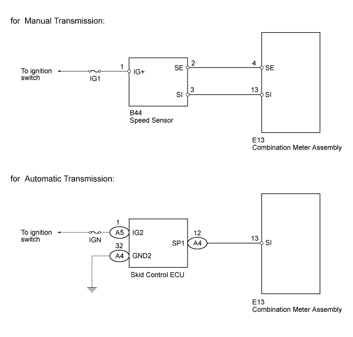

INSPECTION PROCEDURE
| 1. INSPECT COMBINATION METER ASSEMBLY |
 |
- Shift the shift lever (for Manual Transmission) or transmission gear selector lever (for Automatic Transmission) to the neutral position.
Jack up the vehicle.
Turn the ignition switch to ON.
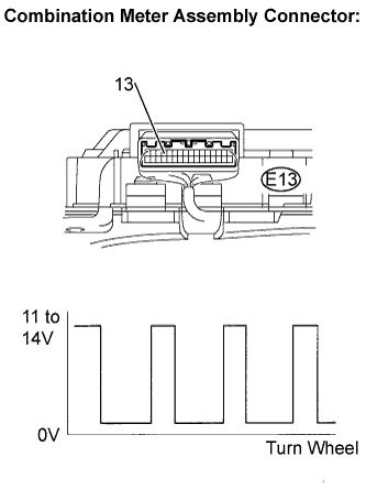
Check the voltage while turning the wheel slowly.
- Standard:
Tester Connection
|
Specified Condition
|
E13-13 (SI) - Body ground
|
Voltage generated intermittently
|
- HINT:
- The output voltage should fluctuate up and down as shown in the diagram on the left when the wheel is turning slowly.
|
NG |
 |
|
|
|
| OK |
|
 |
|
|
| 2. CHECK TRANSAXLE TYPE |
|
Check the vehicle transaxle type.
- Result:
Transaxle Type
|
Proceed to
|
Manual Transmission
|
A
|
Automatic Transmission
|
B
|
|
NG |
 |
|
| READ VALUE USING INTELLIGENT TESTER (VEHICLE SPEED) |
|
|
| OK |
|
 |
|
| 3. INSPECT SPEED SENSOR |
|
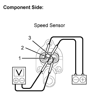
Remove the speed sensor.
Connect the positive (+) lead from the battery to terminal 1 and the negative(-) lead to terminal 2.
Connect the positive (+) lead from the tester to terminal 3 and the negative (-) lead to terminal 2.
Rotate the shaft.
Check that the voltage output between terminals 2 and 3 varies between 0V and 11V.
Reinstall the speed sensor.
|
NG |
|
|
|
|
| OK |
|
|
|
| 4. CHECK HARNESS AND CONNECTOR (SPEED SENSOR - COMBINATION METER ASSEMBLY) |
|
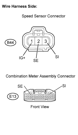
- Disconnect the E13 combination meter assembly connector.
Disconnect the B44 speed sensor connector.
Measure the resistance
- Standard resistance:
Tester Connection
|
Specified Condition
|
E13-13 (SI) - B44-3 (SI)
|
Below 1 Ω
|
B44-2 (SE) - E13-4 (SE)
|
Below 1 Ω
|
Reconnect the combination meter assembly connector.
Measure the voltage
- Standard voltage:
Tester Connection
|
Condition
|
Specified Condition
|
B44-1 (IG+) - Body ground
|
Ignition switch ON
|
11 to 14V
|
Reconnect the speed sensor connector.
|
NG |
|
|
| REPAIR OR REPLACE HARNESS OR CONNECTOR |
|
|
| OK |
|
|
|
|
| 5. READ VALUE USING INTELLIGENT TESTER (VEHICLE SPEED) |
|
Connect the intelligent tester to the DLC3.
Turn the ignition switch to ON.
Turn the tester ON
Enter the following menus: Chassis / ABS/VSC/TRC / Data List.
According to the display on the tester, read the Data List.
ABS/VSC/TRC
Tester Display
|
Measurement Item/Range
|
Normal Condition
|
Diagnostic Note
|
Vehicle Speed
|
Maximum wheel speed sensor reading
Min.: 0 km/h (0 mph)
Max.: 326 km/h (202 mph)
|
Actual vehicle speed
|
Speed indicated on speedometer
|
- OK:
- Vehicle speed displayed on the tester is approximately the same as the actual vehicle speed.
|
NG |
|
|
|
|
| OK |
|
|
|
| 6. CHECK HARNESS AND CONNECTOR (SKID CONTROL ECU - COMBINATION METER ASSEMBLY) |
|
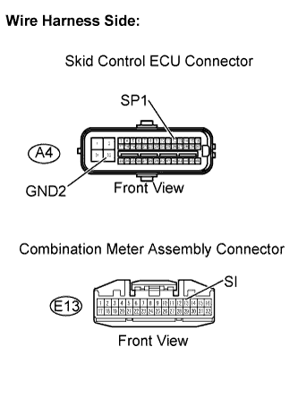
Disconnect the E13 combination meter assembly connector.
Disconnect the A4 skid control ECU connector.
- Measure the resistance.
- Standard resistance:
Tester Connection
|
Specified Condition
|
E13-E13 (SI) - A4-12 (SP1)
|
Below 1 Ω
|
A4-32 (GND2) - Body ground
|
Below 1 Ω
|
|
NG |
|
|
|
|
| OK |
|
|
|
|