Tachometer Malfunction
Circuit diagnosis · Vehicles built Aug 2009 – Oct 2010
Versions by build date: Jul 2007 – Jul 2009 Aug 2009 – Oct 2010 Nov 2010 – Jul 2011 from Aug 2011
DESCRIPTION
The combination meter assembly controls the tachometer in accordance with engine speed signals from the ECM.WIRING DIAGRAM
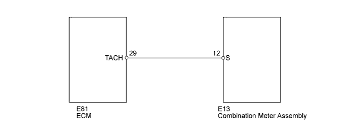

INSPECTION PROCEDURE
| 1. READ VALUE USING INTELLIGENT TESTER (ENGINE SPEED) |

Connect the intelligent tester to the DLC3.
Turn the ignition switch to ON.
Turn the tester on.
Enter the following menus: Powertrain / Engine and ECT / Data List.
According to the display on the tester, read the Data List.
Engine and ECT Tester Display
Measurement Item/Range
Normal Condition
Diagnostic Note
Engine Speed
Engine speed:
Min.: 0 rpm
Max.: 16383 rpm
650 to 750 rpm: Idling
-
- OK:
- Engine speed displayed on the tester is approximately the same as the actual engine speed.
|
|
||||

| OK | |
 |
| 2. CHECK HARNESS AND CONNECTOR (COMBINATION METER ASSEMBLY - ECM) |
Disconnect the E13 combination meter assembly connector.
Disconnect the E81 ECM connector.
Measure the resistance according to the value(s) in the table below.
- Standard Resistance:
Tester Connection
Condition
Specified Condition
E13-12 (S) - E81-29 (TACH)
Always
Below 1 Ω
E13-12 (S) - Body ground
Always
10 kΩ or higher
E81-29 (TACH) - Body ground
Always
10 kΩ or higher
Reconnect the ECM connector.
Reconnect the combination meter assembly connector.
|
|
||||
| OK | ||
 |
||
| ||