Tachometer Malfunction
Circuit diagnosis · Vehicles built from Aug 2011
Versions by build date: Jul 2007 – Jul 2009 Aug 2009 – Oct 2010 Nov 2010 – Jul 2011 from Aug 2011
DESCRIPTION
In this circuit, the meter CPU receives engine speed signals from the ECM using the CAN communication system (CAN V1 Bus). The meter CPU displays the engine speed calculated based on the data received from the ECM.WIRING DIAGRAM
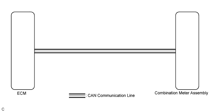

INSPECTION PROCEDURE
| 1. CHECK CAN COMMUNICATION SYSTEM |

Check if a CAN communication DTC is output (Click here).
Result Result
Proceed to
CAN communication DTC is not output
A
CAN communication DTC is output
B
|
|
||||

| A | |
 |
| 2. PERFORM ACTIVE TEST USING INTELLIGENT TESTER (TACHOMETER OPERATION) |
Connect the intelligent tester to the DLC3.
Turn the ignition switch to ON.
Turn the intelligent tester on.
Enter the following menus: Body / Combination Meter / Active Test.
According to the display on the intelligent tester, perform the Active Test.
Combination Meter Tester Display
Test Part
Control Range
Diagnostic Note
TachoMeter Operation
Tachometer
0/1000/2000/3000/4000/5000/6000/7000 rpm
Perform the test with the vehicle stopped and the engine idling.
- OK:
- Tachometer indication is normal.
|
|
||||
| OK | |
|
| 3. READ VALUE USING INTELLIGENT TESTER (ENGINE RPM) |
Connect the intelligent tester to the DLC3.
Start the engine.
Turn the intelligent tester on.
Enter the following menus: Body / Combination Meter / Data List.
According to the display on the intelligent tester, read the Data List.
Combination Meter Tester Display
Measurement Item/Range
Normal Condition
Diagnostic Note
Engine Rpm
Engine speed/
Min.: 0, Max.: 12750
Approximately same as actual engine speed (when engine is running)
Unit: rpm
- OK:
- Engine speed displayed on the intelligent tester is almost the same as the tachometer indication.
- HINT:
- Check the engine speed when the engine is fully warmed up, and the air conditioning and all electrical accessories are off.
|
|
||||
| OK | |
|
| 4. CHECK ENGINE CONTROL SYSTEM |
Check if a engine control DTC is output (Click here).
Result Result
Proceed to
Engine control DTC is not output
A
Engine control DTC is output
B
|
|
||||
| A | ||
 |
||
| ||