Home › BODY ELECTRICAL › AUDIO / VISUAL › RADIO ANTENNA HOLDERREMOVAL
Removal / installation · Vehicles built from Aug 2014
Versions by build date: Jul 2007 – Oct 2010 Nov 2010 – Jul 2011 Aug 2011 – Jul 2012 Aug 2012 – Jul 2013 Aug 2013 – Jul 2014 from Aug 2014
1.
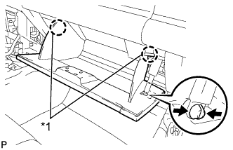
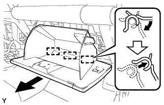
REMOVE GLOVE COMPARTMENT DOOR ASSEMBLY (for LHD)
Disengage the claw and separate the glove compartment door stoppers from the glove compartment door.
Text in Illustration
*1
Stopper
Slightly flex the upper part of the glove compartment door assembly to release the 2 stoppers and open the glove compartment door until it becomes horizontal.
Pull the glove compartment door assembly toward the rear of the vehicle to release the 3 hinges and remove the glove compartment door assembly.
2.
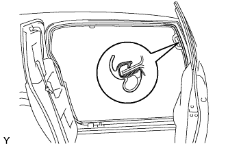
REMOVE FRONT DOOR OPENING TRIM WEATHERSTRIP
Remove the front door opening trim weatherstrip to the extent that the front pillar garnish can be removed.
3.
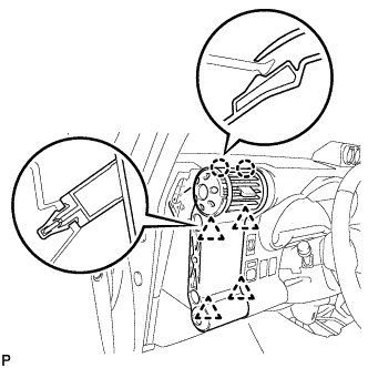
REMOVE NO. 1 INSTRUMENT PANEL REGISTER ASSEMBLY (for RHD)
Disengage the 4 clips and 2 claws and remove the instrument panel register.
NOTICE:
To avoid breakage of the register, remove the instrument panel register with the shut damper of the register open.
Pull the instrument panel register up diagonally to remove it.
4.
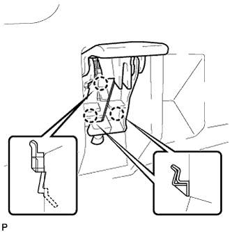
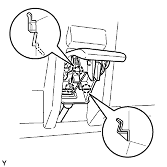
SEPARATE HOOD LOCK CONTROL LEVER SUB-ASSEMBLY (for RHD)
Disengage the 3 claws and separate the hood lock control lever.
5.
SEPARATE FUEL LID LOCK OPEN LEVER SUB-ASSEMBLY (for RHD)
Disengage the 3 claws and separate the fuel lid lock open lever.
6.
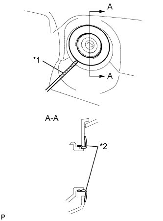
REMOVE INSTRUMENT PANEL FINISH PLATE (for RHD)
Using a screwdriver with its tip wrapped in protective tape, remove the instrument panel finish plate.
Text in Illustration
*1
Protective Tape
*2
Instrument Panel Finish Plate
7.
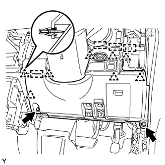
REMOVE LOWER INSTRUMENT PANEL FINISH PANEL (for RHD)
Remove the 2 <E> bolts. Disengage the 8 clips and 4 guides.
Disconnect the connectors and remove the lower instrument panel finish panel.
8.
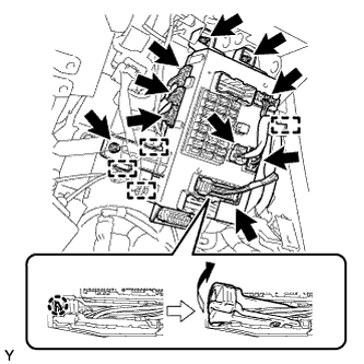
SEPARATE DRIVER SIDE JUNCTION BLOCK (for RHD)
Disconnect the connectors on the front side. Remove the 3 nuts and disconnect the clamps.
Disconnect the connectors on the LH side, and then separate the driver side junction block.
9.
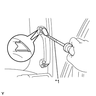
REMOVE ASSIST GRIP PLUG (w/ Assist Grip)
HINT:
Use the same procedure for both sides.
Text in Illustration
*1
Protective Tape
Using a screwdriver with its tip wrapped in protective tape, disengage the 2 claws and remove the assist grip plug.
10.
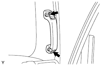
REMOVE ASSIST GRIP ASSEMBLY (w/ Assist Grip)
Remove the 2 screws and the assist grip.
11.
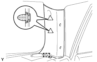
REMOVE FRONT PILLAR GARNISH
w/ Assist Grip:
Disengage the 2 clips and the guide and remove the front pillar garnish.
w/o Assist Grip:
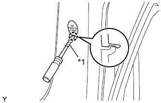
Using a screwdriver with its tip wrapped in protective tape, disengage the claw and open the cover.
Text in Illustration
*1
Protective Tape
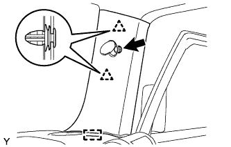
Remove the bolt. Disengage the 2 clips and the guide and remove the front pillar garnish.
12.
REMOVE RADIATOR GRILLE
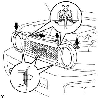
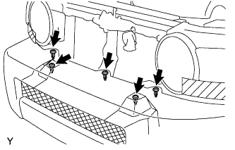
Using a clip remover, remove the 2 clips. Remove the 2 screws.
Disengage the 5 clips and remove the radiator grille.
13.
REMOVE FRONT BUMPER COVER
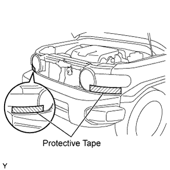
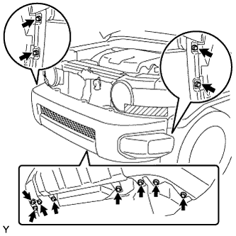
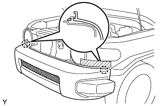
Apply protective tape as shown in the illustration.
Using a clip remover, remove the 5 clips.
Remove the 8 screws and the 4 bolts.
Disengage the 2 claws and remove the front bumper cover.
14.
REMOVE SIDE STEP SUB-ASSEMBLY (w/ Side Step)
HINT:
Use the same procedure as for the LH side (Click here ).
15.
REMOVE ROCKER PANEL MOULDING
HINT:
Use the same procedure as for the LH side (Click here ).
16.
REMOVE FRONT FENDER MUDGUARD
HINT:
Use the same procedure as for the LH side (Click here ).
17.
REMOVE FRONT BUMPER SIDE SUPPORT
HINT:
Use the same procedure as for the LH side (Click here ).
18.
REMOVE FRONT FENDER MOULDING SUB-ASSEMBLY
HINT:
Use the same procedure as for the LH side (Click here ).
19.
REMOVE RADIO ANTENNA POLE SUB-ASSEMBLY
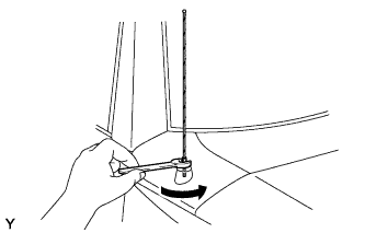
Using a 8 mm (5/16 inch) wrench, remove the radio antenna pole sub-assembly by turning it counterclockwise.
20.
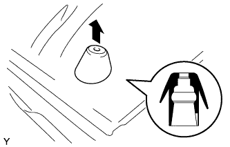
REMOVE ANTENNA ORNAMENT
Pull out the antenna ornament vertically.
21.
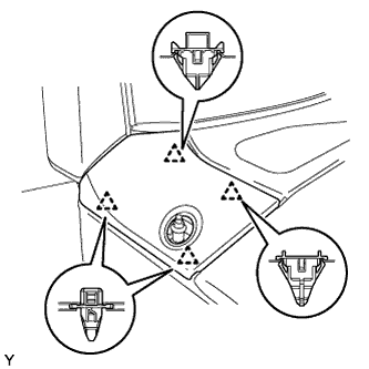
REMOVE FRONT FENDER SIDE UPPER PANEL
Disengage the 4 clips and remove the front fender side panel upper RH. Remove the 4 clips from the front fender side panel upper RH.
22.
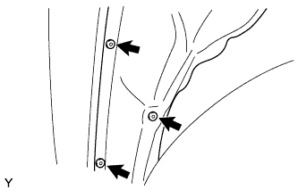
REMOVE FENDER SPLASH REAR SHIELD SUB-ASSEMBLY
Remove the 3 clips and the fender splash rear shield to extent that the radio antenna holder can be removed.
23.
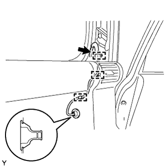
REMOVE RADIO ANTENNA HOLDER ASSEMBLY
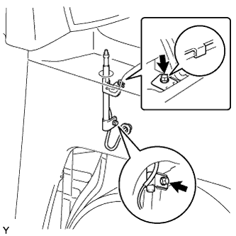
Disconnect the connector. Using a clip remover, remove the 3 clamps and the connector.
Remove the grommet and insert the feeder line through the body hole.
Remove the 2 bolts, the hook and the radio antenna holder.