INSTALLATION
Removal / installation · Vehicles built Aug 2012 – Oct 2012
Versions by build date: Jul 2007 – Oct 2010 Nov 2010 – Jul 2012 Aug 2012 – Oct 2012 from Nov 2012
| 1. INSTALL REAR BUMPER BAR BRACKET LH |

Install the rear bumper bar bracket with the 2 bolts.
- Torque:
- 31 N*m{ 316 kgf*cm , 23 ft.*lbf }
| 2. INSTALL REAR BUMPER BAR BRACKET RH |
Install the rear bumper bar bracket with the 2 bolts.
- Torque:
- 31 N*m{ 316 kgf*cm , 23 ft.*lbf }
| 3. INSTALL REAR BUMPER SIDE SUPPORT SUB-ASSEMBLY LH |
Align the locating 2 guides with the hole and install the rear bumper side support with the 2 bolts.
- Torque:
- 8.0 N*m{ 82 kgf*cm , 71 in.*lbf }
Engage the clamp.
| 4. INSTALL REAR BUMPER SIDE SUPPORT SUB-ASSEMBLY RH |
Align the locating 2 guides with the hole and install the rear bumper side support with the 2 bolts.
- Torque:
- 8.0 N*m{ 82 kgf*cm , 71 in.*lbf }
| 5. INSTALL REAR BUMPER SIDE STAY LH |
Insert the hook into the body hole and install the rear bumper side stay with the bolt.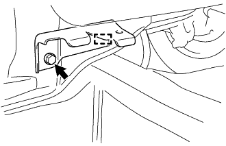

- Torque:
- 8.0 N*m{ 82 kgf*cm , 71 in.*lbf }
| 6. INSTALL REAR BUMPER SIDE STAY RH |
- HINT:
- Use the same procedure as for the LH side.
| 7. INSTALL REAR BUMPER ENERGY ABSORBER |
Install the rear bumper energy absorber.
| 8. INSTALL REAR BUMPER UPPER RETAINER LH |
Engage the 3 claws and install the rear bumper upper retainer.
Install the 2 screws.
- Torque:
- 3.0 N*m{ 31 kgf*cm , 27 in.*lbf }
| 9. INSTALL REAR BUMPER UPPER RETAINER RH |
- HINT:
- Use the same procedure as for the LH side.
| 10. INSTALL REAR BUMPER END RETAINER LH |
Engage the 2 claws and install the rear bumper end retainer.
Install the screw.
- Torque:
- 3.0 N*m{ 31 kgf*cm , 27 in.*lbf }
| 11. INSTALL REAR BUMPER END RETAINER RH |
- HINT:
- Use the same procedure as for the LH side.
| 12. INSTALL REAR BUMPER COVER |
Engage the 6 claws and the 2 clips and install the rear bumper cover.
Engage the harness clamp, and connect the connector.
Tighten the 7 bolts and the 2 screws.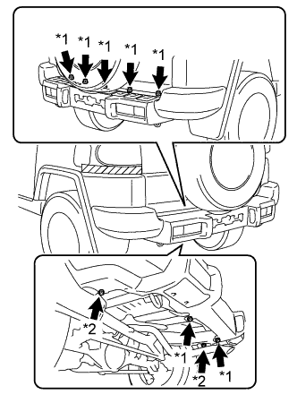
Text in Illustration *1
Bolt
*2
Screw
- Torque:
- 8.0 N*m{ 82 kgf*cm , 71 in.*lbf } for bolt
- 3.0 N*m{ 31 kgf*cm , 27 in.*lbf } for screw
Install the clip.
- HINT:
- Use the same procedure for the RH side and LH side.
Remove the protective tape.