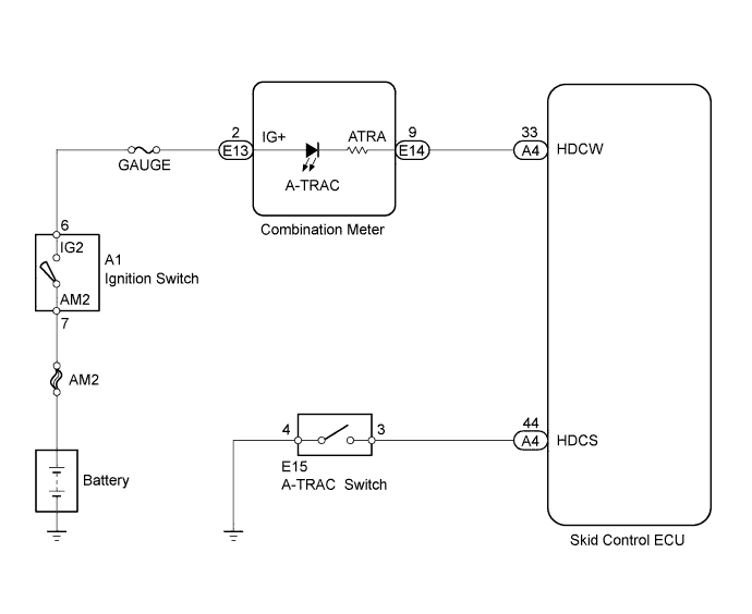
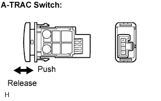
This is the A-TRAC main switch circuit. When the A-TRAC switch is pushed on, the A-TRAC function is available and the A-TRAC indicator light illuminates.
HINT:
The A-TRAC does not operate even if the A-TRAC switch is pressed under the following conditions:
TRC or VSC system is faulty.
Temperature inside the hydraulic brake booster increases and the A-TRAC operation is suspended.
WIRING DIAGRAM
INSPECTION PROCEDURE
NOTICE:
When replacing the master cylinder solenoid, perform zero point calibration (Click here).
1. INSPECT A-TRAC SWITCH
Remove the A-TRAC switch.
Disconnect the A-TRAC switch connector.
Measure the resistance.
Standard resistance:
Tester Connection
Switch Condition
Specified Condition
3 - 4
Released
10 kΩ or higher
3 - 4
Pushed in
Below 1 Ω
NG
REPLACE A-TRAC SWITCH
OK
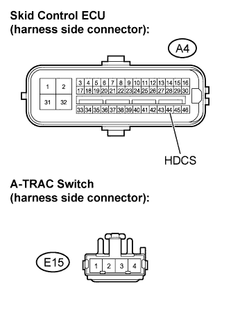
2. CHECK HARNESS AND CONNECTOR (SKID CONTROL ECU - A-TRAC SWITCH)
Disconnect the skid control ECU connector.
Disconnect the A-TRAC connector.
Measure the resistance.
Standard resistance:
Tester Connection
Specified Condition
A4-44 (HDCS) - E15-4
Below 1 Ω
A4-44 (HDCS) - Body ground
10 kΩ or higher
E15-4 - Body ground
Below 1 Ω
NG
REPAIR OR REPLACE HARNESS OR CONNECTOR
OK
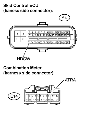
3. CHECK HARNESS AND CONNECTOR (SKID CONTROL ECU - COMBINATION METER)