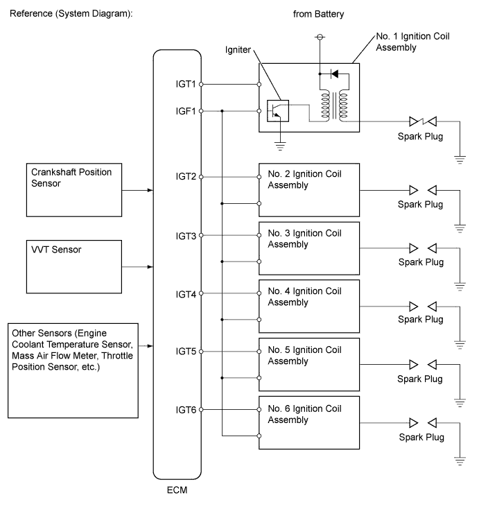
DTC P0351 Ignition Coil "A" Primary / Secondary Circuit |
DTC P0352 Ignition Coil "B" Primary / Secondary Circuit |
DTC P0353 Ignition Coil "C" Primary / Secondary Circuit |
DTC P0354 Ignition Coil "D" Primary / Secondary Circuit |
DTC P0355 Ignition Coil "E" Primary / Secondary Circuit |
DTC P0356 Ignition Coil "F" Primary / Secondary Circuit |
| DTC No. | DTC Detection Condition | Trouble Area |
| P0351 P0352 P0353 P0354 P0355 P0356 | No IGF signal to ECM while engine running (1 trip detection logic) |
|
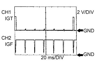
| Item | Content |
| Terminal | CH1: IGT1, IGT2, IGT3, IGT4, IGT5, IGT6 - E1 CH2: IGF1 - E1 |
| Equipment Setting | 2 V/DIV 20 ms/DIV |
| Condition | Idling |
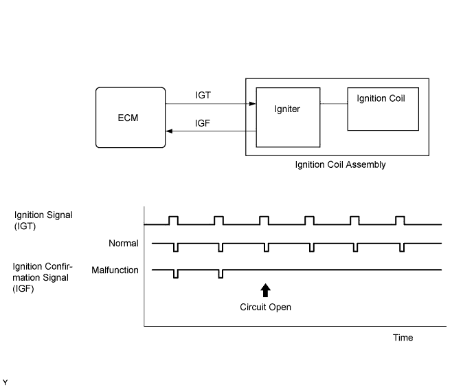
| Related DTCs | P0351: Igniter (Cylinder 1) malfunction P0352: Igniter (Cylinder 2) malfunction P0353: Igniter (Cylinder 3) malfunction P0354: Igniter (Cylinder 4) malfunction P0355: Igniter (Cylinder 5) malfunction P0356: Igniter (Cylinder 6) malfunction |
| Required Sensors/Components (Main) | Ignition coil assembly (Cylinder 1 to 6) |
| Required Sensors/Components (Related) | Crankshaft position sensor |
| Frequency of Operation | Continuous |
| Duration | - |
| MIL Operation | Immediate |
| Sequence of Operation | None |
| Monitor runs whenever following DTCs not present | None |
| All of the following conditions are met | - |
| Spark cut | Not operating |
| Either of following conditions A or B met | - |
| A. Engine speed | 1500 rpm or less |
| B. Starter | OFF |
| Either of following conditions C or D met | - |
| C. Both of following conditions (a) and (b) met | - |
| (a) Engine speed | 500 rpm or less |
| (b) Battery voltage | 6 V or more |
| D. All of following conditions (a), (b) and (c) met | - |
| (a) Engine speed | More than 500 rpm |
| (b) Battery voltage | 10 V or more |
| (c) Number of sparks after CPU reset | 5 sparks or more |
| All of the following conditions are met | A, B, C and D |
| A. Ignition signal fail counter | More than 2 times |
| B. Time after condition A is met | 0.256 seconds or more |
| C. Ignition signal fail count after condition B is met | More than 2 times |
| D. Ignition switch | ON |
| Following condition is met | 2 times or more |
| Confirmed ignition signal | Signal input |
| Techstream Display | Description |
| NORMAL |
|
| ABNORMAL |
|
| INCOMPLETE |
|
| N/A |
|
| 1.CHECK SPARK PLUG AND SPARK OF MISFIRING CYLINDER |
Check the spark plug and sparks of the misfiring cylinder (Click here).
|
| ||||
| OK | |
 |
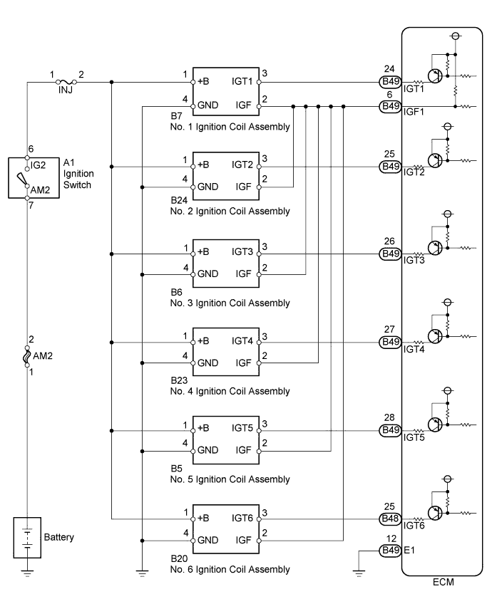
| 2.CHECK HARNESS AND CONNECTOR (IGNITION COIL ASSEMBLY - ECM (IGF1 SIGNAL TERMINAL)) |
Disconnect the B7, B24, B6, B23, B5 and B20 ignition coil assembly connectors.
Disconnect the B49 ECM connector.
Measure the resistance according to the value(s) in the table below.
| Tester Connection | Condition | Specified Condition |
| B7-2 (IGF) - B49-6 (IGF1) | Always | Below 1 Ω |
| B24-2 (IGF) - B49-6 (IGF1) | Always | Below 1 Ω |
| B6-2 (IGF) - B49-6 (IGF1) | Always | Below 1 Ω |
| B23-2 (IGF) - B49-6 (IGF1) | Always | Below 1 Ω |
| B5-2 (IGF) - B49-6 (IGF1) | Always | Below 1 Ω |
| B20-2 (IGF) - B49-6 (IGF1) | Always | Below 1 Ω |
| B7-2 (IGF) or B49-6 (IGF1) - Body ground | Always | 10 kΩ or higher |
| B24-2 (IGF) or B49-6 (IGF1) - Body ground | Always | 10 kΩ or higher |
| B6-2 (IGF) or B49-6 (IGF1) - Body ground | Always | 10 kΩ or higher |
| B23-2 (IGF) or B49-6 (IGF1) - Body ground | Always | 10 kΩ or higher |
| B5-2 (IGF) or B49-6 (IGF1) - Body ground | Always | 10 kΩ or higher |
| B20-2 (IGF) or B49-6 (IGF1) - Body ground | Always | 10 kΩ or higher |
|
| ||||
| OK | |
|
| 3.INSPECT ECM (IGF1 VOLTAGE) |
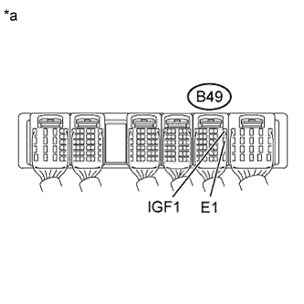 |
Disconnect the B7, B24, B6, B23, B5 and B20 ignition coil assembly connectors.
Turn the ignition switch to ON.
Measure the voltage according to the value(s) in the table below.
| Tester Connection | Switch Condition | Specified Condition |
| B49-6 (IGF1) - B49-12 (E1) | Ignition switch ON | 4.5 to 5.5 V |
| *a | Component with harness connected (ECM) |
|
| ||||
| OK | ||
 | ||
| ||
| 4.CHECK HARNESS AND CONNECTOR (IGNITION COIL ASSEMBLY - ECM (IGT SIGNAL TERMINAL)) |
Disconnect the B7, B24, B6, B23, B5 and B20 ignition coil assembly connectors.
Disconnect the B49 and B48 ECM connectors.
Measure the resistance according to the value(s) in the table below.
| Tester Connection | Condition | Specified Condition |
| B7-3 (IGT1) - B49-24 (IGT1) | Always | Below 1 Ω |
| B24-3 (IGT2) - B49-25 (IGT2) | Always | Below 1 Ω |
| B6-3 (IGT3) - B49-26 (IGT3) | Always | Below 1 Ω |
| B23-3 (IGT4) - B49-27 (IGT4) | Always | Below 1 Ω |
| B5-3 (IGT5) - B49-28 (IGT5) | Always | Below 1 Ω |
| B20-3 (IGT6) - B48-25 (IGT6) | Always | Below 1 Ω |
| B7-3 (IGT1) or B49-24 (IGT1) - Body ground | Always | 10 kΩ or higher |
| B24-3 (IGT2) or B49-25 (IGT2) - Body ground | Always | 10 kΩ or higher |
| B6-3 (IGT3) or B49-26 (IGT3) - Body ground | Always | 10 kΩ or higher |
| B23-3 (IGT4) or B49-27 (IGT4) - Body ground | Always | 10 kΩ or higher |
| B5-3 (IGT5) or B49-28 (IGT5) - Body ground | Always | 10 kΩ or higher |
| B20-3 (IGT6) or B48-25 (IGT6) - Body ground | Always | 10 kΩ or higher |
|
| ||||
| OK | |
|
| 5.INSPECT ECM (IGT1, IGT2, IGT3, IGT4, IGT5, OR IGT6 VOLTAGE) |
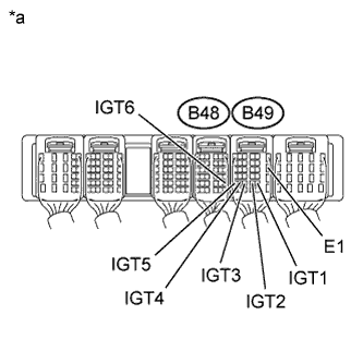 |
Measure the voltage according to the value(s) in the table below, when the engine is cranked.
| Tester Connection | Condition | Specified Condition |
| B49-24 (IGT1) - B49-12 (E1) | Cranking | 0.1 to 4.5 V |
| B49-25 (IGT2) - B49-12 (E1) | Cranking | 0.1 to 4.5 V |
| B49-26 (IGT3) - B49-12 (E1) | Cranking | 0.1 to 4.5 V |
| B49-27 (IGT4) - B49-12 (E1) | Cranking | 0.1 to 4.5 V |
| B49-28 (IGT5) - B49-12 (E1) | Cranking | 0.1 to 4.5 V |
| B48-25 (IGT6) - B49-12 (E1) | Cranking | 0.1 to 4.5 V |
| *a | Component with harness connected (ECM) |
|
| ||||
| OK | |
|
| 6.INSPECT ECM (IGT1, IGT2, IGT3, IGT4, IGT5, OR IGT6 VOLTAGE) |
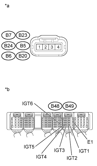 |
Disconnect the ignition coil assembly connectors.
Measure the voltage according to the value(s) in the table below, when the engine is cranked.
| Tester Connections | Condition | Specified Conditions |
| B49-24 (IGT1) - B49-12 (E1) | Cranking | 4.5 V or more |
| B49-25 (IGT2) - B49-12 (E1) | Cranking | 4.5 V or more |
| B49-26 (IGT3) - B49-12 (E1) | Cranking | 4.5 V or more |
| B49-27 (IGT4) - B49-12 (E1) | Cranking | 4.5 V or more |
| B49-28 (IGT5) - B49-12 (E1) | Cranking | 4.5 V or more |
| B48-25 (IGT6) - B49-12 (E1) | Cranking | 4.5 V or more |
| *a | Front view of wire harness connector (to Ignition Coil Assembly) |
| *b | Component with harness connected (ECM) |
|
| ||||
| OK | |
|
| 7.INSPECT IGNITION COIL ASSEMBLY (GROUND AND POWER SOURCE) |
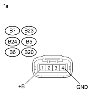 |
Disconnect the ignition coil assembly connectors.
Measure the resistance according to the value(s) in the table below.
| Tester Connection | Condition | Specified Condition |
| B7-4 (GND) - Body ground | Always | Below 1 Ω |
| B24-4 (GND) - Body ground | Always | Below 1 Ω |
| B6-4 (GND) - Body ground | Always | Below 1 Ω |
| B23-4 (GND) - Body ground | Always | Below 1 Ω |
| B5-4 (GND) - Body ground | Always | Below 1 Ω |
| B20-4 (GND) - Body ground | Always | Below 1 Ω |
Turn the ignition switch to ON.
Measure the voltage according to the value(s) in the table below.
| Tester Connection | Switch Condition | Specified Condition |
| B7-1 (+B) - B7-4 (GND) | Ignition switch ON | 11 to 14 V |
| B24-1 (+B) - B24-4 (GND) | Ignition switch ON | 11 to 14 V |
| B6-1 (+B) - B6-4 (GND) | Ignition switch ON | 11 to 14 V |
| B23-1 (+B) - B23-4 (GND) | Ignition switch ON | 11 to 14 V |
| B5-1 (+B) - B5-4 (GND) | Ignition switch ON | 11 to 14 V |
| B20-1 (+B) - B20-4 (GND) | Ignition switch ON | 11 to 14 V |
| *a | Front view of wire harness connector (to Ignition Coil Assembly) |
|
| ||||
| OK | ||
| ||
| ||
| 8.CHECK HARNESS AND CONNECTOR (IGNITION COIL ASSEMBLY - IGNITION SWITCH) |
Disconnect the B7, B24, B6, B23, B5 and B20 ignition coil assembly connectors.
Disconnect the A1 ignition switch connector.
Measure the resistance according to the value(s) in the table below.
| Tester Connection | Condition | Specified Condition |
| B7-1 (+B) - A1-6 (IG2) | Always | Below 1 Ω |
| B24-1 (+B) - A1-6 (IG2) | Always | Below 1 Ω |
| B6-1 (+B) - A1-6 (IG2) | Always | Below 1 Ω |
| B23-1 (+B) - A1-6 (IG2) | Always | Below 1 Ω |
| B5-1 (+B) - A1-6 (IG2) | Always | Below 1 Ω |
| B20-1 (+B) - A1-6 (IG2) | Always | Below 1 Ω |
| B7-1 (+B) or A1-6 (IG2) - Body ground | Always | 10 kΩ or higher |
| B24-1 (+B) or A1-6 (IG2) - Body ground | Always | 10 kΩ or higher |
| B6-1 (+B) or A1-6 (IG2) - Body ground | Always | 10 kΩ or higher |
| B23-1 (+B) or A1-6 (IG2) - Body ground | Always | 10 kΩ or higher |
| B5-1 (+B) or A1-6 (IG2) - Body ground | Always | 10 kΩ or higher |
| B20-1 (+B) or A1-6 (IG2) - Body ground | Always | 10 kΩ or higher |
|
| ||||
| OK | ||
| ||
| ||

