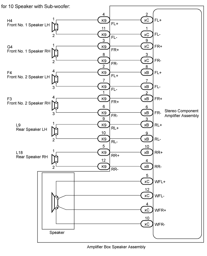
DTC 74-40 Short in Speaker Circuit |
| DTC No. | DTC Detection Condition | Trouble Area |
| 74-40 | Short is detected in the speaker output circuit. |
|
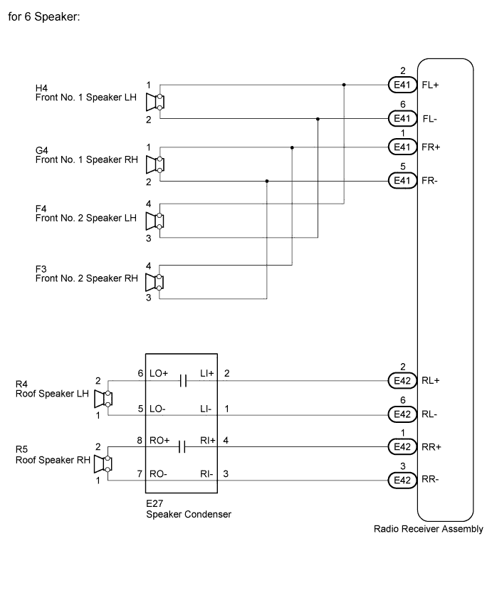
| 1.CONFIRM MODEL |
| Result | Proceed to |
| for 10 speaker with sub-woofer | A |
| for 6 speaker | B |
|
| ||||
| A | |
 |
| 2.CHECK DTC |
Disconnect the K9 amplifier connector.
Clear the DTCs.
Check if DTC 74-40 is output.
|
| ||||
| OK | |
|
| 3.CHECK HARNESS AND CONNECTOR (STEREO COMPONENT AMPLIFIER - SPEAKERS) |
Disconnect the K9 amplifier connector.
Measure the resistance according to the value(s) in the table below.
| Tester Connection | Condition | Specified Condition |
| K9-4 (FL+) - Body ground | Always | 10 kΩ or higher |
| K9-11 (FL-) - Body ground | Always | 10 kΩ or higher |
| K9-3 (FR+) - Body ground | Always | 10 kΩ or higher |
| K9-8 (FR-) - Body ground | Always | 10 kΩ or higher |
| K9-2 (FL+) - Body ground | Always | 10 kΩ or higher |
| K9-7 (FL-) - Body ground | Always | 10 kΩ or higher |
| K9-1 (FR+) - Body ground | Always | 10 kΩ or higher |
| K9-6 (FR-) - Body ground | Always | 10 kΩ or higher |
| K9-9 (RL+) - Body ground | Always | 10 kΩ or higher |
| K9-10 (RL-) - Body ground | Always | 10 kΩ or higher |
| K9-5 (RR+) - Body ground | Always | 10 kΩ or higher |
| K9-12 (RR-) - Body ground | Always | 10 kΩ or higher |
|
| ||||
| OK | |
|
| 4.INSPECT FRONT NO. 1 SPEAKER ASSEMBLY |
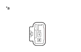 |
Disconnect the H4 and G4 speaker connectors.
Measure the resistance according to the value(s) in the table below.
| Tester Connection | Condition | Specified Condition |
| 1 - 2 | Always | Approximately 1.8 Ω |
| *a | Component without harness connected (Front No. 1 Speaker) |
|
| ||||
| OK | |
|
| 5.INSPECT FRONT NO. 2 SPEAKER ASSEMBLY |
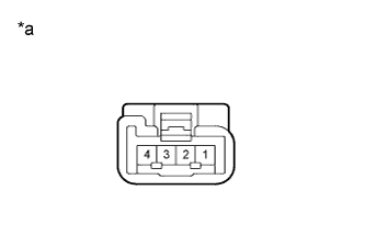 |
Disconnect the F3 and F4 speaker connectors.
Measure the resistance according to the value(s) in the table below.
| Tester Connection | Condition | Specified Condition |
| 3 - 4 | Always | Approximately 1.9 Ω |
| *a | Component without harness connected (Front No. 2 Speaker) |
|
| ||||
| OK | |
|
| 6.INSPECT REAR SPEAKER ASSEMBLY |
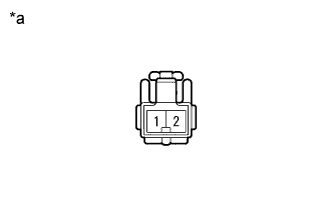 |
Disconnect the L9 and L18 speaker connectors.
Measure the resistance according to the value(s) in the table below.
| Tester Connection | Condition | Specified Condition |
| 1 - 2 | Always | Approximately 1.9 Ω |
| *a | Component without harness connected (Rear Speaker) |
|
| ||||
| OK | |
|
| 7.INSPECT AMPLIFIER BOX SPEAKER ASSEMBLY |
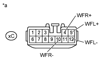 |
Remove the amplifier box speaker assembly (Click here).
Remove the stereo component amplifier assembly from amplifier box speaker assembly (Click here).
Measure the resistance according to the value(s) in the table below.
| Tester Connection | Condition | Specified Condition |
| xC-5 (WFL+) - xC-12 (WFL-) | Always | Approximately 2 Ω |
| xC-4 (WFR+) - xC-10 (WFR-) | Always | Approximately 2 Ω |
| xC-5 (WFL+) - Body ground | Always | 10 kΩ or higher |
| xC-12 (WFL-) - Body ground | Always | 10 kΩ or higher |
| xC-4 (WFR+) - Body ground | Always | 10 kΩ or higher |
| xC-10 (WFR-) - Body ground | Always | 10 kΩ or higher |
| *a | Component without harness connected (Amplifier Box Speaker Assembly) |
|
| ||||
| OK | ||
 | ||
| ||
| 8.CHECK DTC |
Disconnect the E41 and E42 radio receiver connectors.
Clear the DTCs.
Check if DTC 74-40 is output.
|
| ||||
| OK | |
|
| 9.CHECK DTC |
Reconnect the E42 radio receiver connector.
Clear the DTCs.
Check if DTC 74-40 is output.
|
| ||||
| OK | |
|
| 10.CHECK HARNESS AND CONNECTOR (RADIO RECEIVER ASSEMBLY - SPEAKER) |
Disconnect the E41 radio receiver connector.
Measure the resistance according to the value(s) in the table below.
| Tester Connection | Condition | Specified Condition |
| E41-2 (FL+) - Body ground | Always | 10 kΩ or higher |
| E41-6 (FL-) - Body ground | Always | 10 kΩ or higher |
| E41-1 (FR+) - Body ground | Always | 10 kΩ or higher |
| E41-5 (FR-) - Body ground | Always | 10 kΩ or higher |
|
| ||||
| OK | |
|
| 11.INSPECT FRONT NO. 1 SPEAKER ASSEMBLY |
|
Disconnect the H4 and G4 speaker connectors.
Measure the resistance according to the value(s) in the table below.
| Tester Connection | Condition | Specified Condition |
| 1 - 2 | Always | Approximately 4 Ω |
| *a | Component without harness connected (Front No. 1 Speaker) |
|
| ||||
| OK | |
|
| 12.INSPECT FRONT NO. 2 SPEAKER ASSEMBLY |
|
Disconnect the F3 and F4 speaker connectors.
Measure the resistance according to the value(s) in the table below.
| Tester Connection | Condition | Specified Condition |
| 3 - 4 | Always | Approximately 8 Ω |
| *a | Component without harness connected (Front No. 2 Speaker) |
|
| ||||
| OK | ||
| ||
| ||
| 13.CHECK HARNESS AND CONNECTOR (RADIO RECEIVER ASSEMBLY - SPEAKER) |
Disconnect the E42 radio receiver connector.
Measure the resistance according to the value(s) in the table below.
| Tester Connection | Condition | Specified Condition |
| E42-2 (RL+) - Body ground | Always | 10 kΩ or higher |
| E42-6 (RL-) - Body ground | Always | 10 kΩ or higher |
| E42-1 (RR+) - Body ground | Always | 10 kΩ or higher |
| E42-3 (RR-) - Body ground | Always | 10 kΩ or higher |
|
| ||||
| OK | |
|
| 14.INSPECT ROOF SPEAKER ASSEMBLY |
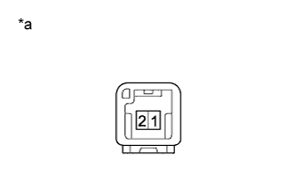 |
Disconnect the R4 and R5 speaker connectors.
Measure the resistance according to the value(s) in the table below.
| Tester Connection | Condition | Specified Condition |
| 1 - 2 | Always | Approximately 4 Ω |
| *a | Component without harness connected (Roof Speaker) |
|
| ||||
| OK | |
|
| 15.CHECK HARNESS AND CONNECTOR (RADIO RECEIVER - SPEAKER CONDENSER) |
Disconnect the E42 receiver connector.
Disconnect the E27 condenser connector.
Measure the resistance according to the value(s) in the table below.
| Tester Connection | Condition | Specified Condition |
| E42-2 (RL+) - E27-2 (LI+) | Always | Below 1 Ω |
| E42-6 (RL-) - E27-1 (LI-) | Always | Below 1 Ω |
| E42-1 (RR+) - E27-4 (RI+) | Always | Below 1 Ω |
| E42-3 (RR-) - E27-3 (RI-) | Always | Below 1 Ω |
|
| ||||
| OK | |
|
| 16.CHECK HARNESS AND CONNECTOR (SPEAKER CONDENSER - ROOF SPEAKER) |
Disconnect the E27 condenser connector.
Disconnect the R4 and R5 speaker connectors.
Measure the resistance according to the value(s) in the table below.
| Tester Connection | Condition | Specified Condition |
| E27-6 (LO+) - R4-2 | Always | Below 1 Ω |
| E27-5 (LO-) - R4-1 | Always | Below 1 Ω |
| E27-8 (RO+) - R5-2 | Always | Below 1 Ω |
| E27-7 (RO-) - R5-1 | Always | Below 1 Ω |
| E27-6 (LO+) - Body ground | Always | 10 kΩ or higher |
| E27-5 (LO-) - Body ground | Always | 10 kΩ or higher |
| E27-8 (RO+) - Body ground | Always | 10 kΩ or higher |
| E27-7 (RO-) - Body ground | Always | 10 kΩ or higher |
|
| ||||
| OK | |
|
| 17.REPLACE SPEAKER CONDENSER |
Temporarily replace the condenser with a new or normally functioning one.
Check that the sound is normal.
|
| ||||
| OK | ||
| ||
| ||

