REAR CRANKSHAFT OIL SEAL > INSTALLATION |
| 1. INSTALL REAR CRANKSHAFT OIL SEAL |
|
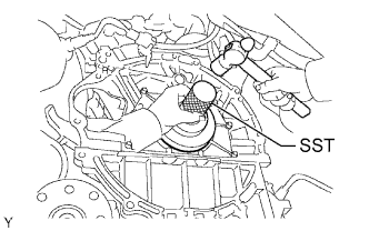
Apply MP grease to the lip of a new oil seal.
Using SST and a hammer, tap in the oil seal until its surface is flush with the rear oil seal retainer edge.
| 2. INSTALL FLYWHEEL SUB-ASSEMBLY (for Manual Transmission) |
Using SST, hold the crankshaft.
Temporarily install the flywheel with the 8 new bolts.
Install and tighten the 8 mounting bolts uniformly in several steps.
Mark the top of the bolts with paint.
Tighten the 8 bolts 90° in the same sequence.
Check that the paint marks are now at a 90° angle to the top.
| 3. INSTALL CLUTCH DISC ASSEMBLY (for Manual Transmission) |
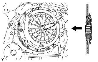 |
Insert SST into the clutch disc assembly, then insert them into the flywheel sub-assembly.
| 4. INSTALL CLUTCH COVER ASSEMBLY (for Manual Transmission) |
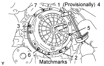 |
Align the matchmarks on the clutch cover assembly and flywheel sub-assembly.
Following the procedures shown in the illustration, tighten the 6 bolts, in the order starting with the bolt located near the knock pin on the top.
| 5. INSPECT AND ADJUST CLUTCH COVER ASSEMBLY (for Manual Transmission) |
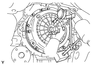 |
Using a dial indicator with roller instrument, check the diaphragm spring tip alignment.
| 6. INSTALL DRIVE PLATE AND RING GEAR SUB-ASSEMBLY (for Automatic Transmission) |
Using SST, hold the crankshaft.
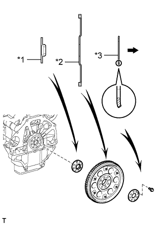 |
Install the front drive plate spacer, drive plate and ring gear and rear drive plate spacer onto the crankshaft.
| *1 | Front Drive Plate Spacer |
| *2 | Drive Plate and Ring Gear |
| *3 | Rear Drive Plate Spacer |
 | Transmission Side |
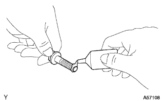 |
Apply adhesive to the 2 or 3 end threads of the bolts.
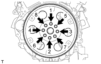 |
Uniformly install and tighten the 8 bolts in several steps in the sequence shown in the illustration.
| 7. INSTALL MANUAL TRANSMISSION UNIT ASSEMBLY (for Manual Transmission) |
| 8. INSTALL AUTOMATIC TRANSMISSION ASSEMBLY (for Automatic Transmission) |