REMOVAL
Removal / installation · Vehicles built from Jan 2015
| 1. REMOVE MANUAL TRANSMISSION ASSEMBLY (for Manual Transmission) |

| 2. REMOVE AUTOMATIC TRANSMISSION ASSEMBLY (for Automatic Transmission) |
| 3. REMOVE CHAIN SUB-ASSEMBLY |
| 4. REMOVE CAMSHAFT BEARING CAP |
Uniformly loosen and remove the 20 bearing cap bolts in the sequence shown in the illustration.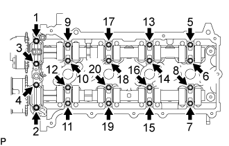

- NOTICE:
- Uniformly loosen the bolts while keeping the camshafts level.
Remove the 9 bearing caps.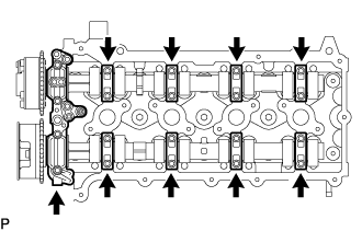
- HINT:
- Arrange the removed parts in the correct order.
| 5. REMOVE CAMSHAFT |
Remove the camshaft.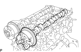
| 6. REMOVE NO. 2 CAMSHAFT |
Remove the No. 2 camshaft.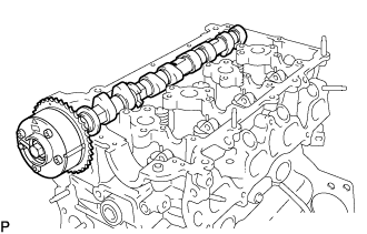
| 7. REMOVE NO. 1 VALVE ROCKER ARM SUB-ASSEMBLY |
Remove the 16 No. 1 valve rocker arm sub-assemblies from the cylinder head sub-assembly.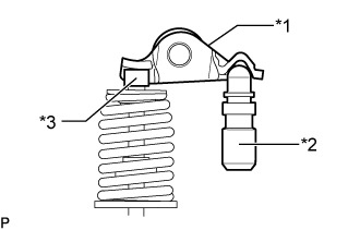
Text in Illustration *1
No. 1 Valve Rocker Arm Sub-assembly
*2
Valve Lash Adjuster Assembly
*3
Valve Stem Cap
- HINT:
- Arrange the removed parts in the correct order.
| 8. REMOVE VALVE LASH ADJUSTER ASSEMBLY |
Remove the 16 valve lash adjuster assemblies from the cylinder head sub-assembly.
- HINT:
- Arrange the removed parts in the correct order.
| 9. REMOVE VALVE STEM CAP |
Remove the 16 valve stem caps from the cylinder head sub-assembly.
- HINT:
- Arrange the removed parts in the correct order.
| 10. REMOVE CYLINDER HEAD SUB-ASSEMBLY |
Uniformly loosen the 10 bolts in the sequence shown in the illustration. Remove the 10 cylinder head bolts and plate washers.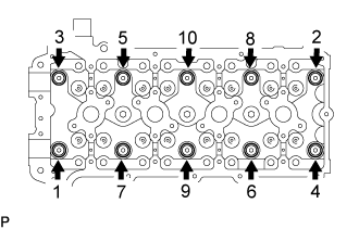
- NOTICE:
- Be careful not to drop plate washers into the cylinder head sub-assembly.
- Head warpage or cracking could result from removing bolts in the incorrect order.
- Be careful not to drop plate washers into the cylinder head sub-assembly.
Remove the cylinder head sub-assembly.
| 11. REMOVE CYLINDER HEAD GASKET |
| 12. INSPECT CYLINDER HEAD SET BOLT |
Using a vernier caliper, measure the diameter of the most elongated threads in the measuring area.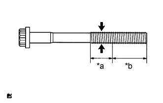
- Standard outside diameter:
- 10.76 to 10.97 mm (0.424 to 0.432 in.)
- Minimum outside diameter:
- 10.40 mm (0.409 in.)
- Distance:
- 30 mm (1.18 in.)
If a visual check reveals no excessively thin areas, check the center of the measuring area (see illustration) and find the area that has the smallest diameter.Text in Illustration *a
Measuring area
*b
Distance
If the diameter is less than the minimum, replace the cylinder head set bolt.
| 13. INSPECT CYLINDER HEAD SUB-ASSEMBLY |
Using a precision straightedge and feeler gauge, measure the warpage of the contact surface of the cylinder block and manifolds.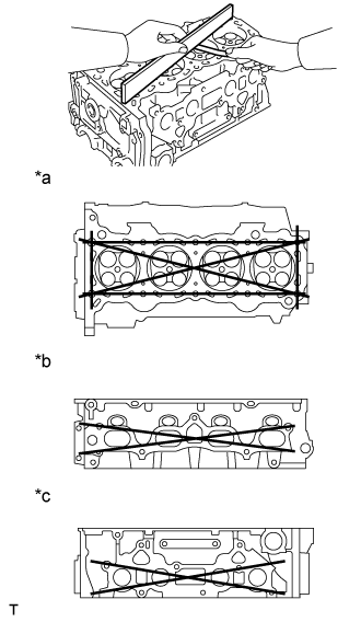
- Maximum warpage:
- 0.05 mm (0.00197 in.)
If the warpage is more than the maximum, replace the cylinder head sub-assembly.Text in Illustration *a
Cylinder Block Side
*b
Intake Manifold Side
*c
Exhaust Manifold Side
Using a dye penetrant, check the intake ports, exhaust ports and cylinder surface for cracks.
If cracked, replace the cylinder head sub-assembly.