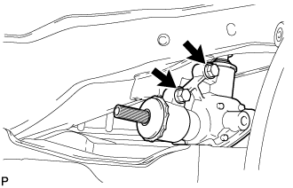
REMOVAL
Removal / installation · Vehicles built from Oct 2014
| 1. PLACE FRONT WHEELS FACING STRAIGHT AHEAD |
| 2. REMOVE STEERING COLUMN HOLE COVER |

Remove 3 bolts and the steering column hole cover.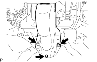

| 3. SEPARATE STEERING INTERMEDIATE SHAFT ASSEMBLY NO.2 |
Fix the steering wheel with the seat belt in order to prevent rotation.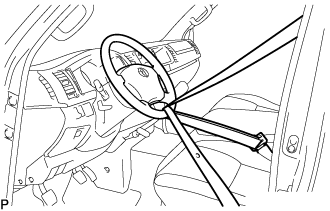
- HINT:
- This operation is useful to prevent damage to the spiral cable.
Loosen bolt (A) and remove bolt (B), then slide the steering intermediate shaft assembly No.2.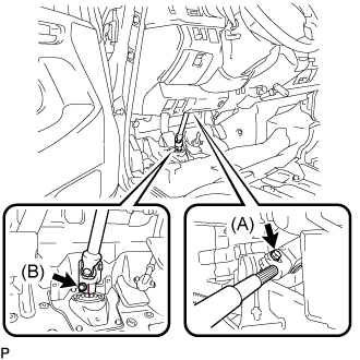
- HINT:
- Do not remove bolt (A).
- Do not disconnect the steering intermediate shaft assembly No.2 from the steering intermediate shaft.
- Do not remove bolt (A).
Put matchmarks on the steering intermediate shaft assembly No.2 and the steering intermediate shaft.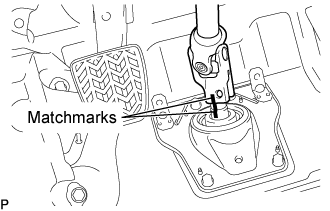
Separate the steering intermediate shaft assembly No.2 from the steering intermediate shaft.
| 4. REMOVE STEERING COLUMN HOLE COVER SUB-ASSEMBLY NO.1 |
Remove the 4 bolts and the steering column hole cover sub-assembly No.1.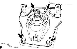
| 5. REMOVE STEERING INTERMEDIATE SHAFT |
Put matchmarks on the steering intermediate shaft and the steering bevel gear assembly.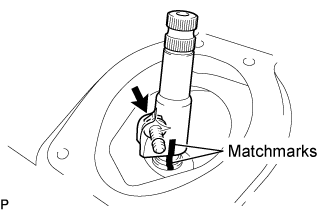
Remove the bolt and the steering intermediate shaft from the steering bevel gear assembly.
| 6. REMOVE ENGINE UNDER COVER NO.1 |
| 7. REMOVE FAN BRACKET SUB-ASSEMBLY |
| 8. DISCONNECT OIL COOLER HOSE (for Automatic Transmission) |
| 9. REMOVE FAN SHROUD |
| 10. SEPARATE STEERING SLIDING YOKE SUB-ASSEMBLY |
Loosen bolt (A) and remove bolt (B), then slide the steering sliding yoke sub-assembly.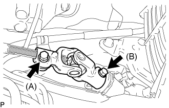
- HINT:
- Do not remove bolt (A).
- Do not disconnect the steering sliding yoke sub-assembly from the steering bevel gear assembly.
- Do not remove bolt (A).
Put matchmarks on the steering sliding yoke sub-assembly from the steering bevel gear assembly.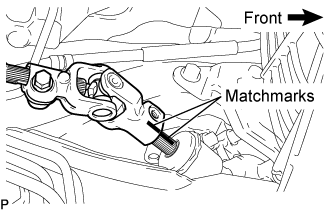
Separate the steering sliding yoke sub-assembly from the steering bevel gear assembly.
| 11. REMOVE STEERING BEVEL GEAR HOUSING BRACKET |
Remove the 3 bolts and the steering bevel gear housing bracket.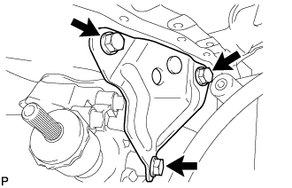
| 12. REMOVE STEERING BEVEL GEAR ASSEMBLY |
Remove the 2 bolts and the steering bevel gear assembly.