Pre-heating Control Circuit
Circuit diagnosis · Vehicles built from Oct 2014
DESCRIPTION
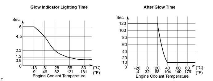
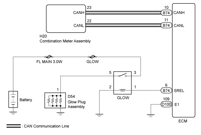
When the ignition switch turns ON, the ECM calculates the glow indicator lighting time/heating corresponding to the coolant temperature at that time and turns on the glow indicator light/GLOW relay.As the ceramics is used for a glow plug material, the current control is not performed.

WIRING DIAGRAM
INSPECTION PROCEDURE
- NOTICE:
- Inspect the fuses for circuits related to this system before performing the following inspection procedure.
| 1. CHECK GLOW INDICATOR LIGHT |

Turn the ignition switch to ON.
Check that the glow indicator light comes on.
- OK:
- The glow indicator light remains on for 0.5 second or more and then goes off.
|
|
||||
|
|
||||

| 2. CHECK WHETHER DTC OUTPUT RECURS |
Connect the GTS to the DLC3.
Turn the ignition switch to ON.
Turn the GTS on.
Enter the following menus: System Select / Health Check.
Check the DTCs.
Result Result
Proceed to
DTC is not output
A
Any DTC is output
B
|
|
||||

| A | |
 |
| 3. PERFORM ACTIVE TEST USING GTS |
Connect the GTS to the DLC3.
Turn the ignition switch to ON.
Turn the GTS on.
Enter the following menus: Body Electrical / Combination Meter / Active Test / Indicat GLOW.
Check the status of the MIL while performing the Active Test.
Result Result
Proceed to
Changes
A
Does not change
B
|
|
||||
| A | |
|
| 4. INSPECT GLOW PLUG ASSEMBLY (INSTALLATION) |
Check that the glow plug and glow plug wire are securely installed.
- OK:
- The glow plug and glow plug wire are securely installed.
|
|
||||
| OK | |
|
| 5. INSPECT GLOW PLUG ASSEMBLY |
Measure the resistance according to the value(s) in the table below.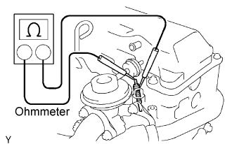
- Standard resistance:
- 0.72 Ω at 20°C (68°F)
- HINT:
- The higher the atmospheric temperature is the larger the resistance becomes and vice versa.
|
|
||||
| OK | |
|
| 6. CHECK FOR INDICATOR LIGHTING TIME AND AFTER GLOW TIME |
Check for indicator lighting time and after glow time (Click here).
|
|
||||
| OK | |
|
| 7. INSPECT GLOW RELAY |
Measure the resistance according to the value(s) in the table below.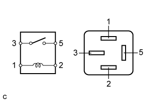
- Standard Resistance:
Tester Connection
Specified Condition
3 - 5
10 kΩ or higher
3 - 5
Below 1 Ω
(When battery voltage is applied to terminals 1 and 2)
|
|
||||
| OK | |
|
| 8. CHECK HARNESS AND CONNECTOR (ECM - GLOW RELAY, GLOW RELAY - BODY GROUND) |
Disconnect the ECM connector.
Disconnect the GLOW relay from the No. 1 engine room relay block and junction block.
Measure the resistance according to the value(s) in the table below.
- Standard Resistance:
Tester Connection
Condition
Specified Condition
GLOW relay terminal 1 - B74-6 (SREL)
Always
Below 1 Ω
GLOW relay terminal 2 - Body ground
Always
Below 1 Ω
B74-6 (SREL) - Body ground
Always
10 kΩ or higher
|
|
||||
| OK | |
|
| 9. CHECK HARNESS AND CONNECTOR (GLOW RELAY - GLOW PLUG ASSEMBLY, GLOW RELAY - BATTERY) |
Disconnect the battery negative cable.
Disconnect the battery positive cable.
Remove the GLOW relay from the No. 1 engine room block and junction block.
Disconnect the glow plug wire.
Measure the resistance according to the value(s) in the table below.
- Standard Resistance:
Tester Connection
Condition
Specified Condition
Glow plug relay terminal 5 - D54-1
Always
Below 1 Ω
Glow plug relay terminal 3 - Positive terminal of the battery
Always
Below 1 Ω
- NOTICE:
- After reconnecting the battery cable, the radio and clock should be adjusted as they were previously.
|
|
||||
| OK | ||
 |
||
| ||