Home › BODY ELECTRICAL › DOOR LOCK › POWER DOOR LOCK CONTROL SYSTEMDoor Control Switch Circuit
Circuit diagnosis · Vehicles built Jan 2015 – Dec 2016
Versions by build date: Oct 2014 – Dec 2014 Jan 2015 – Dec 2016 from Jan 2017
DESCRIPTION
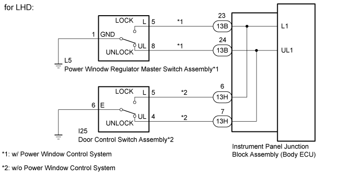
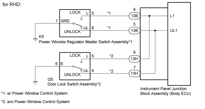
The instrument panel junction block assembly (body ECU) receivers the door lock/unlock request signal from the power window regulator master switch assembly*1 or door control switch assembly*2. The instrument panel junction block assembly (body ECU) actives the door lock motor on all door according to the signal.
*1: w/ Power Window Control System
*2: w/o Power Window Control System
WIRING DIAGRAM
INSPECTION PROCEDURE
1. CHECK VEHICLE TYPE
Check the vehicle type.
Result
Result
Proceed to
w/ Power Window Control System
A
w/o Power Window Control System
B
B
A
2. INSPECT POWER WINDOW REGULATOR MASTER SWITCH ASSEMBLY (DOOR CONTROL SWITCH)
Remove the power window regulator master switch assembly (Click here ).
Inspect the power window regulator master switch assembly (Click here ).
NG
REPLACE POWER WINDOW REGULATOR MASTER SWITCH ASSEMBLY (Click here )
OK
3. CHECK HARNESS AND CONNECTOR (INSTRUMENT PANEL JUNCTION BLOCK ASSEMBLY [BODY ECU] - POWER WINDOW REGULATOR MASTER SWITCH ASSEMBLY AND BODY GROUND)
Disconnect the 13B instrument panel junction block assembly (body ECU) connector.
Disconnect the L5*1 or K5*2 power window regulator master switch assembly connector.
*1: for LHD
*2: for RHD
Measure the resistance according to the value(s) in the table below.
Standard Resistance:
for LHD:
Tester Connection
Condition
Specified Condition
13B-23 (L1) - L5-5 (L)
Always
Below 1 Ω
13B-24 (UL1) - L5-8 (UL)
Always
Below 1 Ω
L5-1 (GND) - Body ground
Always
Below 1 Ω
13B-23 (L1) or L5-5 (L) - Body ground
Always
10 kΩ or higher
13B-24 (UL1) or L5-8 (UL) - Body ground
Always
10 kΩ or higher
for RHD:
Tester Connection
Condition
Specified Condition
13B-6 (L1) - K5-5 (L)
Always
Below 1 Ω
13B-5 (UL1) - K5-8 (UL)
Always
Below 1 Ω
K5-1 (GND) - Body ground
Always
Below 1 Ω
13B-6 (L1) or K5-5 (L) - Body ground
Always
10 kΩ or higher
13B-5 (UL1) or K5-8 (UL) - Body ground
Always
10 kΩ or higher
NG
REPAIR OR REPLACE HARNESS OR CONNECTOR
OK
PROCEED TO NEXT CIRCUIT INSPECTION SHOWN IN PROBLEM SYMPTOMS TABLE (Click here )
4. INSPECT DOOR CONTROL SWITCH ASSEMBLY
Remove the door control switch assembly.
Inspect the door control switch assembly (Click here ).
NG
REPLACE DOOR CONTROL SWITCH ASSEMBLY
OK
5. CHECK HARNESS AND CONNECTOR (INSTRUMENT PANEL JUNCTION BLOCK ASSEMBLY [BODY ECU] - DOOR CONTROL SWITCH ASSEMBLY AND BODY GROUND)
Disconnect the 13H instrument panel junction connector assembly (body ECU) connector.
Disconnect the I25 door control switch assembly connector.
Measure the resistance according to the value(s) in the table below.
Standard Resistance:
Tester Connection
Condition
Specified Condition
13H-6 (L1) - I25-5 (L)
Always
Below 1 Ω
13H-7 (UL1) - I25-4 (UL)
Always
Below 1 Ω
I25-6 (E) - Body ground
Always
Below 1 Ω
13H-6 (L1) or I25-5 (L) - Body ground
Always
10 kΩ or higher
13H-7 (UL1) or I25-4 (UL) - Body ground
Always
10 kΩ or higher
NG
REPAIR OR REPLACE HARNESS OR CONNECTOR
OK
PROCEED TO NEXT CIRCUIT INSPECTION SHOWN IN PROBLEM SYMPTOMS TABLE (Click here )