Open in One Side of CAN Sub Bus Line
Circuit diagnosis · Vehicles built Apr 2016 – Dec 2016
Versions by build date: Oct 2014 – Dec 2014 Jan 2015 – Mar 2016 Apr 2016 – Dec 2016 from Jan 2017
DESCRIPTION
If 2 or more ECUs and/or sensors do not appear on the GTS "Bus Check" screen, one side of the CAN branch wire may be open (one side of the CANH [CAN branch wire]/CANL [CAN branch wire] of the ECU and/or sensor is open).| Symptom |
Trouble Area |
| 2 or more ECUs and/or sensors do not appear on the GTS "Bus Check" screen. |
|
- *1: w/ Air Conditioning System, except 5L-E
- *2: w/ Smart Entry and Start System
- *3: for LED Headlight
- *4: w/ Airbag System
- *5: w/ ABS
- *6: w/ VSC
WIRING DIAGRAM
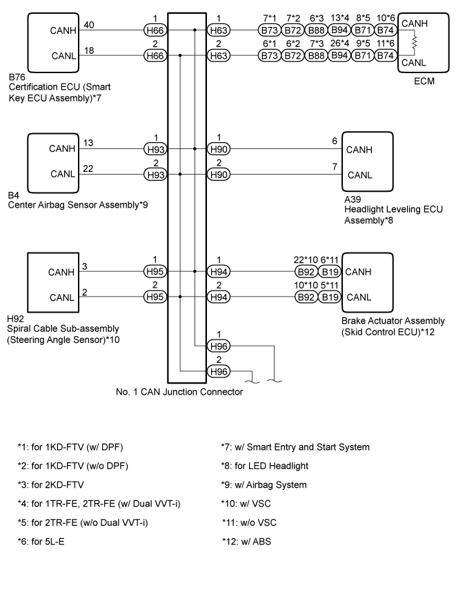

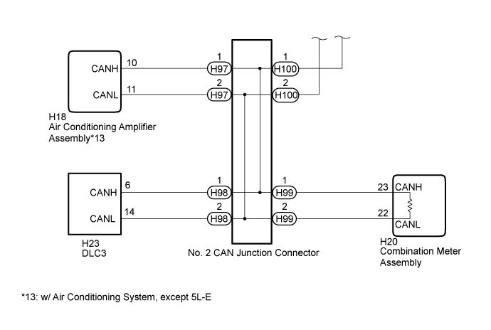
INSPECTION PROCEDURE
- NOTICE:
- For vehicles with a smart entry and start system:
- Before replacing the certification ECU (smart key ECU assembly), refer to the smart entry and start system (Click here).
- HINT:
- Perform the following inspection for the ECUs (sensors) which are not displayed on the GTS. If a malfunction cannot be identified, perform the following inspections for the ECUs (sensors) connected to the CAN communication system.
- Do not remove the combination meter assembly and ECM, as they are the end parts of the circuit. If removed, CAN communication will not be possible.
- The open circuit confirmation of the combination meter assembly, ECM and CAN main wire is performed in the Check CAN Bus Line procedure of "How to Proceed with Troubleshooting". This inspection only has procedures for checking for an open circuit on one side of the CAN branch wire.
- Perform the following inspection for the ECUs (sensors) which are not displayed on the GTS. If a malfunction cannot be identified, perform the following inspections for the ECUs (sensors) connected to the CAN communication system.
| 1. CHECK FOR OPEN IN ONE SIDE OF CAN BRANCH WIRE (CERTIFICATION ECU) |

- NOTICE:
- For vehicles without a smart entry and start system, go to "Check for Open in One Side of CAN Branch Wire (Headlight Leveling ECU Assembly)".
Disconnect the B76 certification ECU (smart key ECU assembly) connector.
Select "Bus Check" on the GTS (Click here).
Result Result
Proceed to
"Certification (Smart)" not displayed on the GTS.
A
Several ECUs and sensors in addition to "Certification (Smart)" not displayed on the GTS.
B
|
|
||||

| A | |
 |
| 2. CHECK FOR OPEN IN ONE SIDE OF CAN BRANCH WIRE (CERTIFICATION ECU CAN BRANCH WIRE) |
Disconnect the cable from the negative (-) battery terminal before measuring the resistances of the CAN main wire and the CAN branch wire.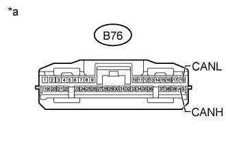
- CAUTION:
- For vehicles with an airbag system:
- Wait at least 90 seconds after disconnecting the cable from the negative (-) battery terminal to disable the SRS system.
- NOTICE:
- When disconnecting the cable, some systems need to be initialized after the cable is reconnected (Click here).
Measure the resistance according to the value(s) in the table below.
- Standard Resistance:
Tester Connection
Switch Condition
Specified Condition
B76-40 (CANH) - B76-18 (CANL)
Ignition switch off
54 to 69 Ω
Text in Illustration *a
Front view of wire harness connector
(to Certification ECU [Smart Key ECU Assembly])
|
|
||||

| OK | ||
 |
||
| ||
| 3. CHECK FOR OPEN IN ONE SIDE OF CAN BRANCH WIRE (HEADLIGHT LEVELING ECU ASSEMBLY) |
- NOTICE:
- For vehicles with a halogen headlight, go to "Check for Open in One Side of CAN Branch Wire (Center Airbag Sensor Assembly)".
Disconnect the A39 headlight leveling ECU assembly connector.
Select "Bus Check" on the GTS (Click here).
Result Result
Proceed to
"Headlight swivel (AFS)" not displayed on the GTS.
A
Several ECUs and sensors in addition to "Headlight swivel (AFS)" not displayed on the GTS.
B
|
|
||||
| A | |
|
| 4. CHECK FOR OPEN IN ONE SIDE OF CAN BRANCH WIRE (HEADLIGHT LEVELING ECU ASSEMBLY CAN BRANCH WIRE) |
Disconnect the cable from the negative (-) battery terminal before measuring the resistances of the CAN main wire and the CAN branch wire.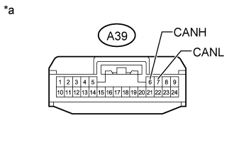
- CAUTION:
- For vehicles with an airbag system:
- Wait at least 90 seconds after disconnecting the cable from the negative (-) battery terminal to disable the SRS system.
- NOTICE:
- When disconnecting the cable, some systems need to be initialized after the cable is reconnected (Click here).
Measure the resistance according to the value(s) in the table below.
- Standard Resistance:
Tester Connection
Switch Condition
Specified Condition
A39-6 (CANH) - A39-7 (CANL)
Ignition switch off
54 to 69 Ω
Text in Illustration *a
Front view of wire harness connector
(to Headlight Leveling ECU Assembly)
Result Result
Proceed to
OK (for LHD)
A
OK (for RHD)
B
NG
C
|
|
||||
|
|
||||
| A | ||
|
||
| ||
| 5. CHECK FOR OPEN IN ONE SIDE OF CAN BRANCH WIRE (CENTER AIRBAG SENSOR ASSEMBLY) |
- NOTICE:
- For vehicles without an airbag system, go to "Check for Open in One Side of CAN Branch Wire (Brake Actuator Assembly)".
Disconnect the B4 center airbag sensor assembly connector.
Select "Bus Check" on the GTS (Click here).
Result Result
Proceed to
"Airbag" not displayed on the GTS.
A
Several ECUs and sensors in addition to "Airbag" not displayed on the GTS.
B
|
|
||||
| A | |
|
| 6. CHECK FOR OPEN IN ONE SIDE OF CAN BRANCH WIRE (CENTER AIRBAG SENSOR ASSEMBLY CAN BRANCH WIRE) |
Disconnect the cable from the negative (-) battery terminal before measuring the resistances of the CAN main wire and the CAN branch wire.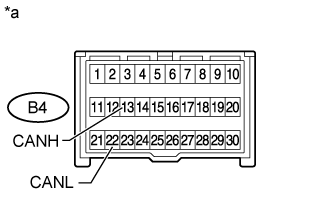
- CAUTION:
- For vehicles with an airbag system:
- Wait at least 90 seconds after disconnecting the cable from the negative (-) battery terminal to disable the SRS system.
- NOTICE:
- When disconnecting the cable, some systems need to be initialized after the cable is reconnected (Click here).
Measure the resistance according to the value(s) in the table below.
- Standard Resistance:
Tester Connection
Switch Condition
Specified Condition
B4-13 (CANH) - B4-22 (CANL)
Ignition switch off
54 to 69 Ω
Text in Illustration *a
Front view of wire harness connector
(to Center Airbag Sensor Assembly)
|
|
||||
| OK | ||
|
||
| ||
| 7. CHECK FOR OPEN IN ONE SIDE OF CAN BRANCH WIRE (BRAKE ACTUATOR ASSEMBLY) |
- NOTICE:
- For vehicles without an ABS, go to "Check for Open in One Side of CAN Branch Wire (Air Conditioning Amplifier Assembly CAN Branch Wire)".
Disconnect the B92*1 or B19*2 brake actuator assembly (skid control ECU) connector.
- *1: w/ VSC
- *2: w/o VSC
- *1: w/ VSC
Select "Bus Check" on the GTS (Click here).
Result Result
Proceed to
"Skid Control (ABS/VSC/TRAC)" not displayed on the GTS.
A
Several ECUs and sensors in addition to "Skid Control (ABS/VSC/TRAC)" not displayed on the GTS.
B
|
|
||||
| A | |
|
| 8. CHECK FOR OPEN IN ONE SIDE OF CAN BRANCH WIRE (BRAKE ACTUATOR ASSEMBLY CAN BRANCH WIRE) |
Disconnect the cable from the negative (-) battery terminal before measuring the resistances of the CAN main wire and the CAN branch wire.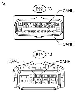
- CAUTION:
- For vehicles with an airbag system:
- Wait at least 90 seconds after disconnecting the cable from the negative (-) battery terminal to disable the SRS system.
- NOTICE:
- When disconnecting the cable, some systems need to be initialized after the cable is reconnected (Click here).
Measure the resistance according to the value(s) in the table below.
- Standard Resistance:
w/ VSC Tester Connection
Switch Condition
Specified Condition
B92-22 (CANH) - B92-10 (CANL)
Ignition switch off
54 to 69 Ω
w/o VSC Tester Connection
Switch Condition
Specified Condition
B19-6 (CANH) - B19-5 (CANL)
Ignition switch off
54 to 69 Ω
Text in Illustration *A
w/ VSC
*B
w/o VSC
*a
Front view of wire harness connector
(to Brake Actuator Assembly [Skid Control ECU])
Result Result
Proceed to
OK (w/ VSC)
A
OK (w/o VSC)
B
NG
C
|
|
||||
|
|
||||
| A | ||
|
||
| ||
| 9. CHECK FOR OPEN IN ONE SIDE OF CAN BRANCH WIRE (SPIRAL CABLE SUB-ASSEMBLY) |
- NOTICE:
- For vehicles without a VSC, go to "Check for Open in One Side of CAN Branch Wire (Air Conditioning Amplifier Assembly CAN Branch Wire)".
Disconnect the H92 spiral cable sub-assembly (steering angle sensor) connector.
Select "Bus Check" on the GTS (Click here).
Result Result
Proceed to
"Spiral cable (Steering Angle Sensor)" not displayed on the GTS.
A
Several ECUs and sensors in addition to "Spiral cable (Steering Angle Sensor)" not displayed on the GTS.
B
|
|
||||
| A | |
|
| 10. CHECK FOR OPEN IN ONE SIDE OF CAN BRANCH WIRE (SPIRAL CABLE SUB-ASSEMBLY CAN BRANCH WIRE) |
Disconnect the cable from the negative (-) battery terminal before measuring the resistances of the CAN main wire and the CAN branch wire.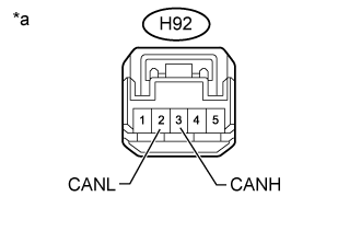
- CAUTION:
- For vehicles with an airbag system:
- Wait at least 90 seconds after disconnecting the cable from the negative (-) battery terminal to disable the SRS system.
- NOTICE:
- When disconnecting the cable, some systems need to be initialized after the cable is reconnected (Click here).
Measure the resistance according to the value(s) in the table below.
- Standard Resistance:
Tester Connection
Switch Condition
Specified Condition
H92-3 (CANH) - H92-2 (CANL)
Ignition switch off
54 to 69 Ω
Text in Illustration *a
Front view of wire harness connector
(to Spiral Cable Sub-assembly [Steering Angle Sensor])
|
|
||||
| OK | ||
|
||
| ||
| 11. CHECK FOR OPEN IN ONE SIDE OF CAN BRANCH WIRE (AIR CONDITIONING AMPLIFIER ASSEMBLY CAN BRANCH WIRE) |
- NOTICE:
- For vehicles without an air conditioning system or with 5L-E engine type, go to "How to Proceed with Troubleshooting".
Disconnect the cable from the negative (-) battery terminal before measuring the resistances of the CAN main wire and the CAN branch wire.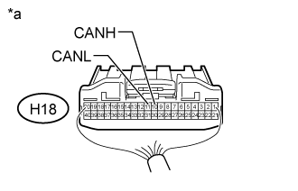
- CAUTION:
- For vehicles with an airbag system:
- Wait at least 90 seconds after disconnecting the cable from the negative (-) battery terminal to disable the SRS system.
- NOTICE:
- When disconnecting the cable, some systems need to be initialized after the cable is reconnected (Click here).
Disconnect the air conditioning amplifier assembly connector.
Measure the resistance according to the value(s) in the table below.
- Standard Resistance:
Tester Connection
Switch Condition
Specified Condition
H18-10 (CANH) - H18-11 (CANL)
Ignition switch off
54 to 69 Ω
Text in Illustration *a
Rear view of wire harness connector
(to Air Conditioning Amplifier Assembly)
|
|
||||
| OK | ||
|
||
| ||