REMOVAL
Removal / installation · Vehicles built from Jan 2017
- NOTICE:
- When replacing the parts in the following chart (A), replace the No. 1 injection pipe sub-assembly, No. 2 injection pipe sub-assembly and/or fuel inlet pipe sub-assembly with new ones.
Replaced Parts (A)
Pipes Requiring New Replacement
- Injector assembly (including shuffling the injector assemblies between the cylinders)
- Common rail assembly
- Injection pipe sub-assembly or supply pump assembly
- No. 1 injection pipe sub-assembly
- No. 2 injection pipe sub-assembly
Common rail assembly
Fuel inlet pipe sub-assembly
- Injection pipe sub-assembly or supply pump assembly
- Cylinder block sub-assembly
- Cylinder head sub-assembly
- Cylinder head gasket
- Timing chain case assembly or belt cover sub-assembly
- No. 1 injection pipe sub-assembly
- No. 2 injection pipe sub-assembly
- Fuel inlet pipe sub-assembly
- Injector assembly (including shuffling the injector assemblies between the cylinders)
- After removing the No. 1 injection pipe sub-assembly, No. 2 injection pipe sub-assembly and/or fuel inlet pipe sub-assembly, clean them with a brush and compressed air.
- When replacing the parts in the following chart (A), replace the No. 1 injection pipe sub-assembly, No. 2 injection pipe sub-assembly and/or fuel inlet pipe sub-assembly with new ones.
| 1. DISCONNECT CABLE FROM NEGATIVE BATTERY TERMINAL |

- NOTICE:
- When disconnecting the cable, some systems need to be initialized after the cable is reconnected (Click here).
| 2. REMOVE EGR COOLER ASSEMBLY |
| 3. REMOVE ENGINE OIL LEVEL DIPSTICK GUIDE |
w/ No. 2 Fuel Pipe Clamp: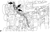

Detach the No. 2 fuel pipe clamp from the engine oil level dipstick guide.
Remove the engine oil level dipstick.
Slide the clip and disconnect vacuum hose from the intake manifold.
Remove the bolt and engine oil level dipstick guide.
Remove the O-ring and grommet from the engine oil level dipstick guide.
| 4. DISCONNECT NO. 2 FUEL PIPE |
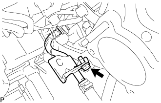 |
Remove the bolt and disconnect the No. 2 fuel pipe.
| 5. REMOVE WIRING HARNESS CLAMP BRACKET |
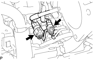 |
Disconnect the diesel throttle body assembly connector and pre-stroke control valve connector.
Detach the 2 wire harness clamps.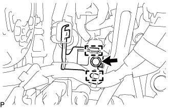
Remove the bolt and wiring harness clamp bracket.
| 6. REMOVE MANIFOLD STAY |
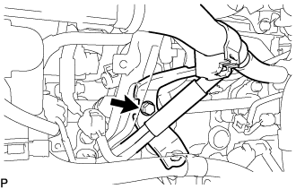 |
Remove the bolt and disconnect the wiring harness clamp bracket from the manifold stay.
Remove the 2 bolts and manifold stay.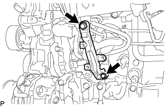
| 7. REMOVE NO. 4 FUEL PIPE SUB-ASSEMBLY |
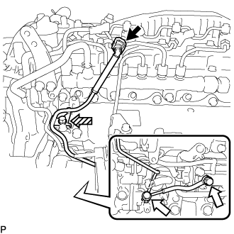 |
Disconnect the No. 4 fuel pipe sub-assembly from the No. 1 fuel pipe (Click here).
Text in Illustration 
Union Bolt
Bolt
Remove the bolt from the intake manifold.
Remove the 2 union bolts and 2 gaskets from the supply pump assembly and fuel filter.
| 8. REMOVE NO. 3 FUEL PIPE |
Remove the union bolts, supply pump hollow screw and 2 gaskets from the supply pump assembly and fuel filter.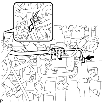
Text in Illustration 
Union Bolt

Supply Pump Hollow Screw
Remove the 2 fuel pipe clamps from the No. 3 fuel pipe and fuel filter.
| 9. REMOVE FUEL INLET PIPE SUB-ASSEMBLY |
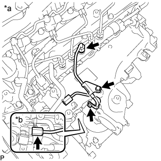 |
| *a |
Common Rail Assembly Side |
| *b |
Fuel Supply Pump Assembly Side |
Remove the 2 bolts, No. 1 injection pipe clamp and No. 2 injection pipe clamp.
Using SST, loosen the fuel inlet pipe sub-assembly union nut of the common rail assembly side.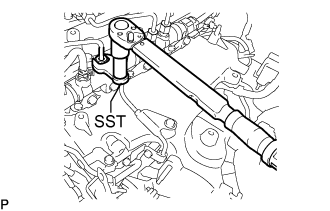
- SST
- 09245-11010
- NOTICE:
- If the No. 1 or No. 2 injection pipe clamp is removed from the inlet pipe sub-assembly, replace the No. 1 or No. 2 injection clamp with a new one.
Using a 19 mm union nut wrench, loosen the inlet pipe sub-assembly union nut of the fuel supply pump assembly side.
| 10. REMOVE NO. 2 NOZZLE LEAKAGE PIPE ASSEMBLY |
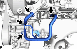 |
Slide the 2 clamps and remove the No. 4 fuel hose from the No. 2 nozzle leakage pipe assembly and common rail assembly.
Slide the 2 clamps and remove the No. 5 fuel hose from the No. 1 nozzle leakage pipe assembly and No. 2 nozzle leakage pipe assembly.
Slide the clamp and disconnect the No. 6 fuel hose from the No. 3 nozzle leakage pipe assembly.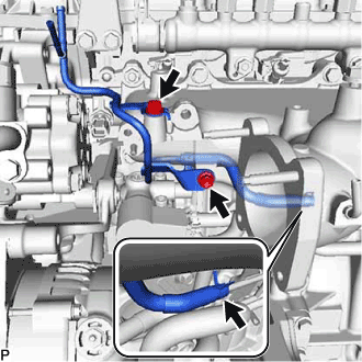
Remove the 2 bolts and No. 2 nozzle leakage pipe assembly.
| 11. REMOVE VACUUM CONTROL VALVE SET |
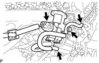 |
Disconnect the wire harness clamp and vacuum control valve set connector.
Disconnect the 2 vacuum hoses from the swirl control valve actuator and vacuum transmitting pipe sub-assembly.
Remove the bolt and vacuum control valve set from the intake manifold.
| 12. REMOVE INTAKE MANIFOLD |
Remove the bolt and disconnect the wire harness bracket.
Remove the 7 bolts, 2 nuts, intake manifold and gasket.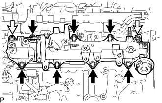
Text in Illustration 
Bolt
Nut