1GD-FTV ENGINE CONTROL ECD SYSTEM(w/ Exhaust Gas Temperature Sensor for EGR) P245700 Exhaust Gas Recirculation Cooler "A" Efficiency Below Threshold
DESCRIPTION
The ECU uses the No. 5 exhaust gas temperature sensor (EGR gas temperature sensor) installed between the electric EGR control valve assembly and intake manifold to monitor the temperature of the exhaust gas introduced into the intake manifold.
The cooling efficiency of the EGR cooler is calculated from the No. 5 exhaust gas temperature sensor (EGR gas temperature sensor), the estimated temperature of the exhaust gas near the exhaust manifold and the engine coolant temperature sensor. If this cooling efficiency is low, it is determined that the efficiency of the EGR cooler has decreased.
| DTC No. | Detection Item | DTC Detection Condition | Trouble Area | MIL | Memory | Note |
|---|---|---|---|---|---|---|
| P245700 | Exhaust Gas Recirculation Cooler "A" Efficiency Below Threshold | Estimated EGR cooler coolant efficiency is below the threshold (2 trip detection logic). | ·
EGR cooler clogging ·
EGR cooler coolant leak ·
No. 2 EGR valve assembly sticking ·
Vacuum pipe ·
No. 5 exhaust gas temperature sensor (EGR gas temperature sensor) |
Class B2 | DTC stored | SAE Code: P2457 |
| DTC No. | Data List |
|---|---|
| P245700 | ·
Coolant Temperature ·
EGR Cooler Bypass VSV ·
EGR Cooler Bypass VSV2 ·
EGR Cooler Bypass Position ·
EGR Temperature B1S1 |
CONFIRMATION DRIVING PATTERN
| DTC No. | DTC Detection Drive Pattern |
|---|---|
| P245700 | Warm up the engine, and then drive the vehicle at a constant speed of 70 km/h (43.8 mph) in 4th gear for 5 minutes.
The EGR cooler cooling efficiency calculated from the stabilized values of "Coolant Temperature" and "EGR Temperature B1S1" and the estimated exhaust gas temperature near the exhaust manifold is 0.56 or more.
|
CAUTION / NOTICE / HINT
- HINT:
-
Read freeze frame data using the GTS. Freeze frame data records the engine condition when malfunctions are detected. When troubleshooting, freeze frame data can help determine if the vehicle was moving or stationary, if the engine was warmed up or not, and other data from the time the malfunction occurred.
PROCEDURE
Connect the GTS to the DLC3.
Turn the engine switch on (IG) and turn the GTS on.
Enter the following menus: Powertrain / Engine and Transmission / Trouble Codes.
Read the DTCs.
- Powertrain > Engine and Transmission > Trouble Codes
- 50001 456
- Result:
Result Proceed to DTC P245700 is output A DTC P245700 and other DTCs are output B
- HINT:
-
If any DTCs other than P245700 are output, troubleshoot those DTCs first.
A
B
Check that no coolant is leaking in the No. 1 EGR cooler due to a disconnected or damaged hose.
- OK:
No leaks.
- Result:
Proceed to OK NG
OK
NG
Connect the GTS to the DLC3.
Start the engine and warm it up, and make sure the A/C switch and all accessory switches are off.
Enter the following menus: Powertrain / Engine and Transmission / Active Test / Activate the EGR Cooler Bypass Control Valve / Data List / EGR Cooler Bypass Position.
- Powertrain > Engine and Transmission > Active Test
-
Active Test Display Activate the EGR Cooler Bypass Control Valve -
Data List Display EGR Cooler Bypass Position - 50004 456 42006 107
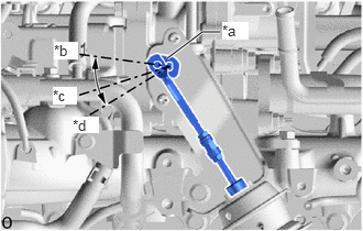
| *a | EGR Cooler By-pass Valve Regulating Link |
| *b | Bypass Position |
| *c | Half Opened Position |
| *d | Cooler Position |
Perform the Active Test and check that the EGR cooler by-pass valve regulating link changes to each position normally.
- Result:
GTS Display Result Proceed to Activate the EGR Cooler Bypass Control Valve:
Bypass → Half Pos → CoolerThe EGR cooler by-pass valve regulating link changes to each position normally A The EGR cooler by-pass valve regulating link does not change to each position normally B
A
B
Remove the No. 1 EGR cooler.
Click hereEngine / Hybrid System>1GD-FTV (EMISSION CONTROL)>EGR COOLER>REMOVAL
Check the accumulation status of deposits in the No. 1 EGR cooler.
- OK:
Not blocked by deposits
- Result:
Proceed to OK NG
OK
NG
Inspect the No. 5 exhaust gas temperature sensor (EGR gas temperature sensor).
- Result:
Proceed to OK NG
OK
NG
Connect the GTS to the DLC3.
Turn the engine switch on (IG).
Turn the GTS on.
Clear the DTCs.
- Powertrain > Engine and Transmission > Clear DTCs
- 50002 456
Turn the engine switch off for 30 seconds or more.
Start the engine and warm it up.
Take a snapshot of the following Data List items.
Enter the following menus: Powertrain / Engine and Transmission / Data List / Coolant Temperature and EGR Temperature B1S1.
- Powertrain > Engine and Transmission > Data List
-
Tester Display Coolant Temperature EGR Temperature B1S1 - 50003 456 237,299
Drive the vehicle at a constant speed of 70 km/h (43.8 mph) in 4th gear for 5 minutes.
Calculate the EGR cooler cooling efficiency from the stabilized values of "Coolant Temperature" and "EGR Temperature B1S1" from the recorded snapshot and the estimated exhaust gas temperature near the exhaust manifold.
- HINT:
- ·
EGR cooler cooling efficiency = (273°C - Value of EGR Temperature B1S1 (°C) / 273°C - Value of Coolant Temperature (°C))
·273°C = The estimated exhaust gas temperature near the exhaust manifold after warming up the engine and driving at a constant speed of 70 km/h (43.8 mph) in 4th gear for 5 minutes.
Check the calculated EGR cooler cooling efficiency.
- Result:
Check that the EGR cooler cooling efficiency is 0.56 or more.
- Result:
Proceed to NEXT
NEXT
Replace the No. 1 EGR cooler.
Click hereEngine / Hybrid System>1GD-FTV (EMISSION CONTROL)>EGR COOLER>REMOVAL
- Result:
Proceed to NEXT
NEXT
Replace the No. 5 exhaust gas temperature sensor (EGR gas temperature sensor).
Click hereEngine / Hybrid System>1GD-FTV (EMISSION CONTROL)>EXHAUST GAS TEMPERATURE SENSOR (for EGR)>REMOVAL
- Result:
Proceed to NEXT
NEXT
Check the connection of the vacuum switching valve assembly (for EGR Bypass Valve) vacuum hose.
Check the connection of the vacuum switching valve assembly (for No. 2 EGR Bypass Valve) vacuum hose.
- Result:
Proceed to NEXT
NEXT
Inspect the No. 2 EGR valve assembly.
Click hereEngine / Hybrid System>1GD-FTV (EMISSION CONTROL)>EGR VALVE (w/ EGR Cooler)>INSPECTION
- Result:
Proceed to OK NG
OK
NG
Replace the No. 2 EGR valve assembly.
Click hereEngine / Hybrid System>1GD-FTV (EMISSION CONTROL)>EGR VALVE (w/ EGR Cooler)>REMOVAL
- Result:
Proceed to NEXT
NEXT
Repair any coolant leaks.
- Result:
Proceed to NEXT
NEXT