1GD-FTV EMISSION CONTROL EXHAUST FUEL ADDITION INJECTOR REMOVAL
CAUTION / NOTICE / HINT
- CAUTION:
-
-
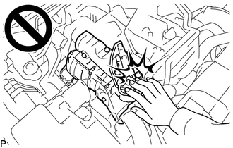
To prevent burns, do not touch the engine, exhaust manifold or other high temperature components while the engine is hot.
PROCEDURE

 1.DRAIN ENGINE COOLANT (for Air Cooled Type Intercooler)
12601B
2.REMOVE NO. 1 ENGINE COVER SUB-ASSEMBLY (w/ Cover)
17940D
3.REMOVE INTERCOOLER ASSEMBLY (for Water Cooled Type Intercooler)
23811H
4.REMOVE NO. 1 FUEL PIPE
- CAUTION:
-
To prevent burns, do not touch the engine, exhaust manifold or other high temperature components while the engine is hot.
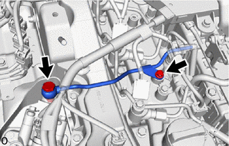
Remove the bolt, union bolt and gasket and disconnect the No. 1 fuel pipe from the cylinder head cover sub-assembly and exhaust fuel addition injector assembly.
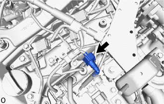
Disconnect the No. 4 fuel pipe and remove the No. 1 fuel pipe.
Click hereEngine / Hybrid System>1GD-FTV (FUEL)>FUEL SYSTEM>PRECAUTION
12229
5.REMOVE PCV PIPE
16281
6.DISCONNECT NO. 4 WATER BY-PASS HOSE
- CAUTION:
-
To prevent burns, do not touch the engine, exhaust manifold or other high temperature components while the engine is hot.
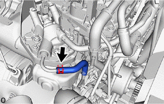
Slide the clamp and disconnect the No. 4 water by-pass hose from the No. 1 injector holder.
16282
7.DISCONNECT NO. 5 WATER BY-PASS HOSE
- CAUTION:
-
To prevent burns, do not touch the engine, exhaust manifold or other high temperature components while the engine is hot.
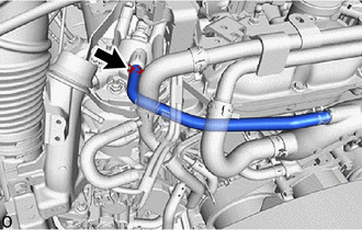
Slide the clamp and disconnect the No. 5 water by-pass hose from the No. 1 injector holder.
23295D
8.REMOVE NO. 1 INJECTOR HOLDER
- CAUTION:
-
To prevent burns, do not touch the engine, exhaust manifold or other high temperature components while the engine is hot.
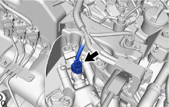
Disconnect the connector from the exhaust fuel addition injector assembly.
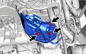
Remove the 3 nuts and No. 1 injector holder from the exhaust manifold.
17168
9.REMOVE NO. 2 EXHAUST MANIFOLD HEAT INSULATOR
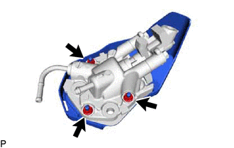
Remove the 3 nuts and No. 2 exhaust manifold heat insulator from the No. 1 injector holder.
Remove the gasket.
23295C
10.REMOVE INJECTOR HOLDER
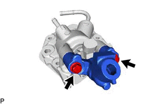
Remove the 2 bolts and injector holder from the No. 1 injector holder.
23695B
11.REMOVE NO. 2 NOZZLE HOLDER CLAMP
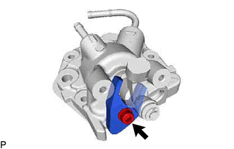
Using a T40 "TORX" socket wrench, remove the bolt and No. 2 nozzle holder clamp from the No. 1 injector holder.
23710B
12.REMOVE EXHAUST FUEL ADDITION INJECTOR ASSEMBLY
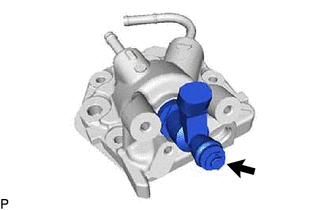
Remove the exhaust fuel addition injector assembly from the No. 1 injector holder.
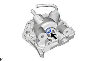
Remove the gasket from the No. 1 injector holder.
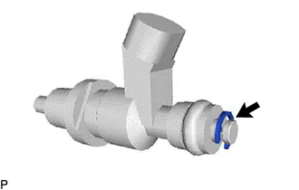
Remove the E-ring from the exhaust fuel addition injector assembly.
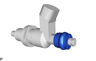
Remove the No. 3 fuel injector back-up ring, O-ring, No. 2 fuel injector back-up ring and No. 1 fuel injector back-up ring from the exhaust fuel addition injector assembly.