1GD-FTV INTAKE / EXHAUST EXHAUST PIPE INSTALLATION
PROCEDURE

 17430
1.INSTALL TAILPIPE ASSEMBLY
Install the tailpipe assembly to the exhaust pipe support.
17420
2.INSTALL CENTER EXHAUST PIPE ASSEMBLY
Connect the center exhaust pipe assembly to the 3 exhaust pipe supports.
Install a new gasket and connect the tailpipe to the center exhaust pipe assembly with the 2 bolts.
- Torque:
- 43 N*m (438 kgf*cm, 32 ft.*lbf)
- NOTICE:
-
Do not reuse the gasket.
89425C
3.INSTALL NO. 4 EXHAUST GAS TEMPERATURE SENSOR (w/ Urea SCR System)
894A0
4.INSTALL PARTICULATE MATTER SENSOR (w/ Particulate Matter Sensor)
89463C
5.INSTALL NITROGEN OXIDES SENSOR (w/ Urea SCR System)
17410
6.INSTALL FRONT EXHAUST PIPE ASSEMBLY
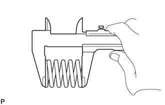
Using a vernier caliper, measure the free length of the compression spring.
- Minimum length:
40.2 mm (1.58 in.)
If the free length is less than the minimum, replace the compression spring.
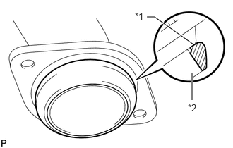
| *1 | Gasket |
| *2 | Exhaust Manifold Converter Sub-assembly or Turbine Outlet Elbow |
Install a new gasket to the exhaust manifold converter sub-assembly or turbine outlet elbow.
- NOTICE:
- ·
Be sure to install the gasket so that it faces the correct direction.
·Do not reuse the gasket.
·Do not damage the gasket.
·When connecting the front exhaust pipe assembly, do not push in the gasket with the front exhaust pipe assembly.
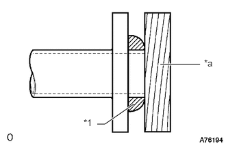
| *1 | Gasket |
| *a | Wooden Block |
Using a plastic-faced hammer and wooden block, tap on a new gasket until its surface is flush with the exhaust manifold converter sub-assembly or turbine outlet elbow.
w/o Urea SCR System:
Install the front exhaust pipe assembly to the exhaust pipe support.
w/ Urea SCR System:
Install the front exhaust pipe assembly to the 2 exhaust pipe supports.
Install the front exhaust pipe assembly and 2 compression springs with the 2 bolts. Alternately tighten the bolts in several passes.
- Torque:
- 43 N*m (438 kgf*cm, 32 ft.*lbf)
23203A
7.INSTALL UREA INJECTOR SET (w/ Urea SCR System)
8.INSPECT FOR EXHAUST GAS LEAK
If gas is leaking, tighten the problem areas to stop the leak. Replace damaged parts as necessary.
51405A
9.INSTALL ENGINE UNDER COVER SUB-ASSEMBLY NO.1
52618
10.INSTALL LOWER FRONT BUMPER ABSORBER
51406A
11.INSTALL NO. 2 ENGINE UNDER COVER SUB-ASSEMBLY (w/ No. 2 Engine Under Cover Sub-assembly)