Home › STEERING › STEERING COLUMN › STEERING COLUMN ASSEMBLYREMOVAL
Removal / installation · Vehicles built from Jul 2010
Versions by build date: May 2007 – Jul 2008 Aug 2008 – Jun 2010 from Jul 2010
CAUTION:
Some of these service operations affect the SRS airbag system. Read the precautionary notices concerning the SRS airbag system before servicing the steering column (Click here ).
1.
PRECAUTION
(Click here )
2.
POSITION FRONT WHEELS STRAIGHT AHEAD
3.
DISCONNECT CABLE FROM NEGATIVE BATTERY TERMINAL
CAUTION:
Wait at least 90 seconds after disconnecting the cable from the negative (-) battery terminal to prevent airbag and seat belt pretensioner activation.
NOTICE:
When disconnecting the cable, some systems need to be initialized after the cable is reconnected (Click here ).
5.
REMOVE STEERING PAD
(Click here )
6.
REMOVE STEERING WHEEL ASSEMBLY
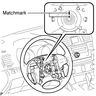
Remove the steering wheel assembly set nut. Put matchmarks on the steering wheel assembly and the steering main shaft.
Disconnect the connectors from the spiral cable.
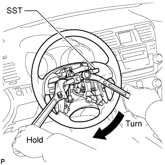
Using SST, remove the steering wheel assembly.
SST
09950-50013
(09951-05010, 09952-05010, 09953-05020, 09954-05021)
NOTICE:
Apply a small amount of grease to the threads and tip of SST (09953-05020) before use.
7.
REMOVE DRIVER SIDE KNEE AIRBAG ASSEMBLY
(Click here )
8.
REMOVE BRAKE PEDAL RETURN SPRING
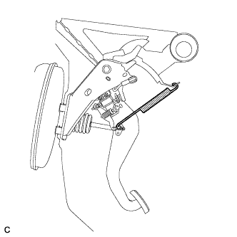
Remove the brake pedal return spring from the push rod pin and instrument panel reinforcement.
9.
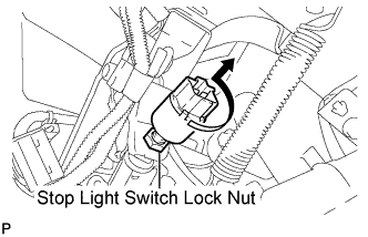
REMOVE STOP LIGHT SWITCH ASSEMBLY
Disconnect the connector.
Loosen the stop light switch lock nut. Remove the stop light switch assembly as shown in the illustration.
10.
SEPARATE BRAKE MASTER CYLINDER PUSH ROD CLEVIS
Remove the clip and push rod pin, and separate the brake master cylinder push rod clevis from the brake pedal sub-assembly.
11.
REMOVE BRAKE PEDAL SUPPORT SUB-ASSEMBLY (for LHD)
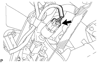
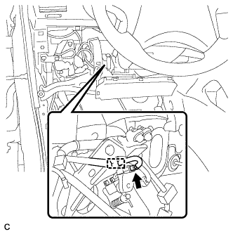
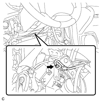
Disconnect the brake pedal load sensing switch connector and disengage the clamp.
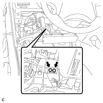
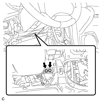
Remove the 2 bolts and separate the brake pedal support sub-assembly from the instrument panel reinforcement.
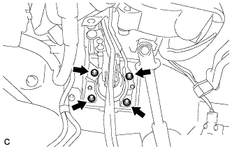
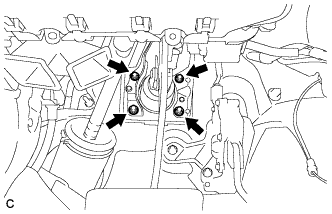
Remove the 4 nuts and brake pedal support sub-assembly from the body.
12.
REMOVE BRAKE PEDAL SUPPORT SUB-ASSEMBLY (for RHD)
Disconnect the brake pedal load sensing switch connector and disengage the clamp.
Remove the 2 bolts and separate the brake pedal support sub-assembly from the instrument panel reinforcement.
Remove the 4 nuts and brake pedal support sub-assembly from the body.
13.
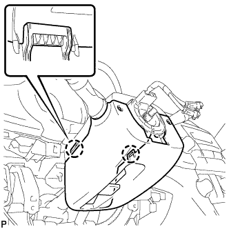
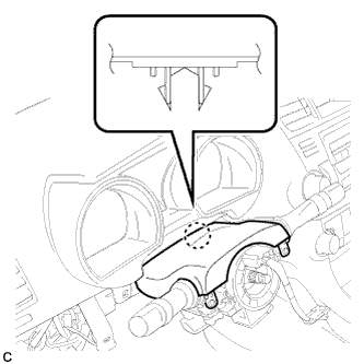
REMOVE STEERING COLUMN COVER
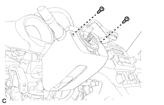
Remove the 2 screws.
Disengage the 2 claws to remove the lower steering column cover.
Disengage the claw to remove the upper steering column cover.
14.
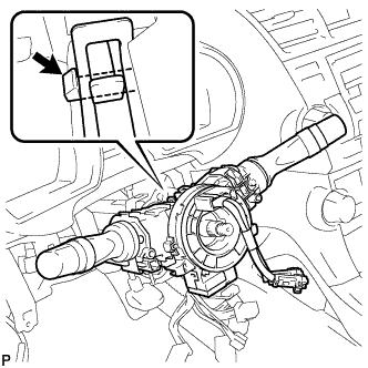
REMOVE TURN SIGNAL SWITCH ASSEMBLY WITH SPIRAL CABLE SUB-ASSEMBLY
Disconnect the connectors from the turn signal switch assembly with spiral cable sub-assembly.
Using pliers, grip the claws of the clip and remove the turn signal switch assembly with spiral cable sub-assembly.
15.
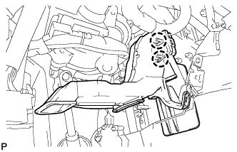
REMOVE NO. 1 AIR DUCT SUB-ASSEMBLY (for LHD)
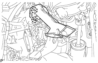
Disengage the 2 claws and remove the No. 1 air duct sub-assembly.
16.
REMOVE NO. 1 AIR DUCT SUB-ASSEMBLY (for RHD)
Disengage the 2 claws and remove the No. 1 air duct sub-assembly.
17.
SEPARATE STEERING INTERMEDIATE SHAFT SUB-ASSEMBLY
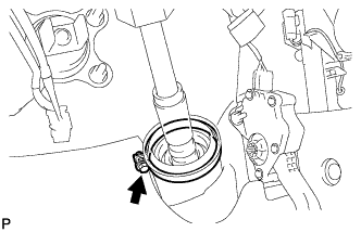
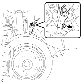
Loosen the bolt.
Remove the bolt and slide the steering intermediate shaft sub-assembly.
NOTICE:
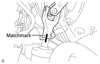
Do not separate the steering intermediate shaft sub-assembly from the power steering link assembly.
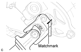
Put matchmarks on the steering intermediate shaft sub-assembly and the power steering link assembly. Separate the steering intermediate shaft sub-assembly from the power steering link assembly.
18.
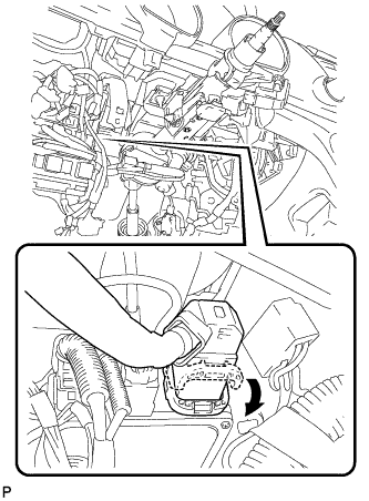
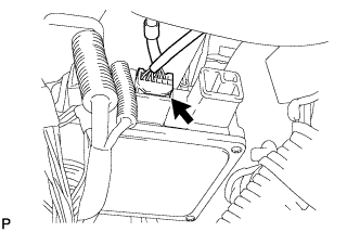
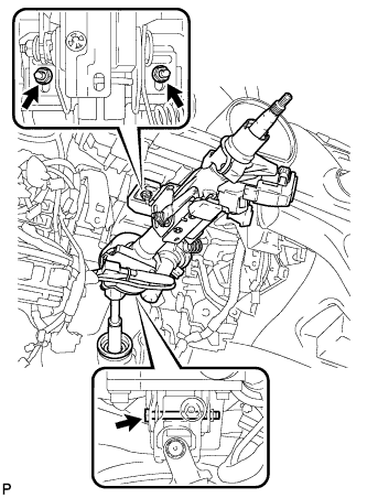
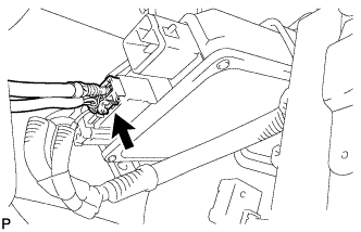
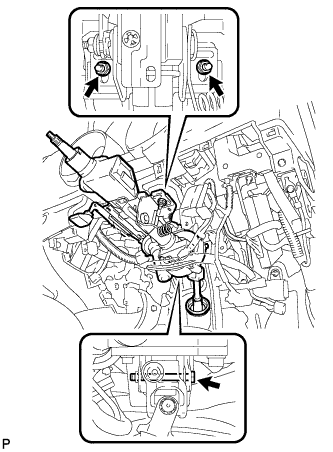
REMOVE STEERING COLUMN ASSEMBLY (for LHD)
Disconnect the connector from the power steering ECU assembly.
HINT:
As shown in the illustration, turn the lock lever to disconnect the connector.
Disconnect the connector from the power steering ECU assembly. Disconnect the connectors and disengage the wire harness clamps from the steering column assembly.
Remove the bolt, 2 nuts, and the steering column assembly.
19.
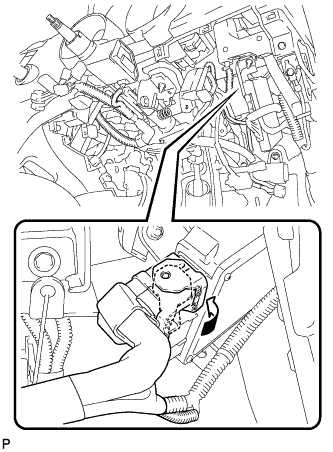
REMOVE STEERING COLUMN ASSEMBLY (for RHD)
Disconnect the connector from the power steering ECU assembly.
HINT:
As shown in the illustration, turn the lock lever to disconnect the connector.
Disconnect the connector from the power steering ECU assembly. Disconnect the connectors and disengage the wire harness clamps from the steering column assembly.
Remove the bolt, 2 nuts, and the steering column assembly.
20.
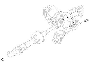
REMOVE STEERING INTERMEDIATE SHAFT SUB-ASSEMBLY
Remove the bolt.
Put matchmarks on the steering intermediate shaft assembly and the steering column assembly. Remove the steering intermediate shaft assembly from the steering column assembly.