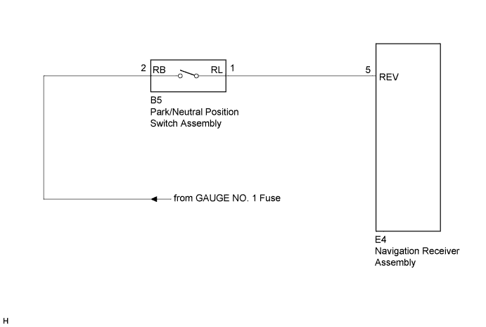
The navigation receiver assembly receives a reverse signal from the park/neutral position switch assembly and information about the navigation antenna assembly, and then adjusts the vehicle position on the navigation display.
WIRING DIAGRAM
INSPECTION PROCEDURE
1. INSPECT NAVIGATION RECEIVER ASSEMBLY
Disconnect the E4 navigation receiver assembly connector.
Measure the voltage according to the value(s) in the table below.
Standard Voltage:
Tester Connection
Condition
Specified Condition
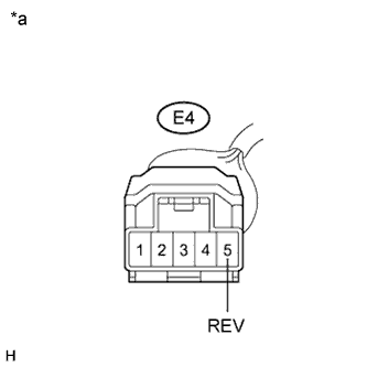
E4-5 (REV) - Body ground
Ignition switch ON Shift lever in R
11 to 14 V
E4-5 (REV) - Body ground
Ignition switch ON Shift lever in any position except R
Below 1 V
Text in Illustration
*a
Front view of wire harness connector (to Navigation Receiver Assembly)