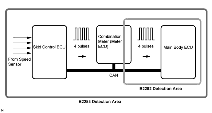
DTC B2282 Vehicle Speed Signal Malfunction |
DTC B2283 Vehicle Speed Sensor Malfunction |
| DTC No. | DTC Detection Condition | Trouble Area |
| B2282 | Cable information and CAN information between the main body ECU (instrument panel junction block) and the combination meter are inconsistent |
|
| B2283 | When either of conditions below is met:
|
|
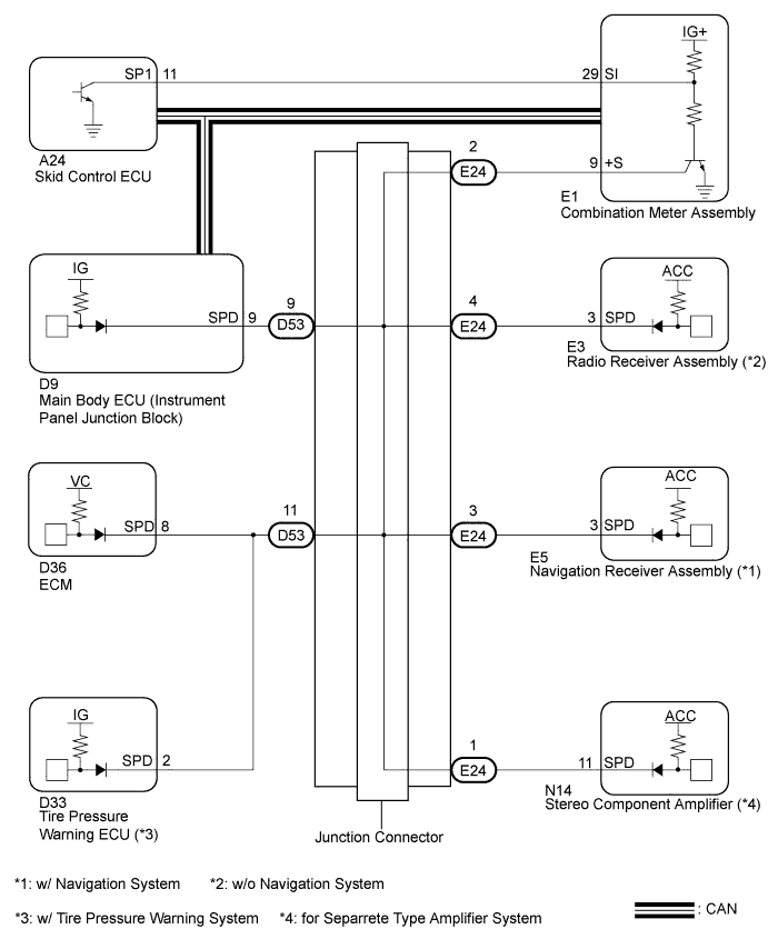
| 1.CHECK CAN COMMUNICATION SYSTEM |
Check for CAN communication system DTCs (Click here).
| Result | Proceed to |
| CAN communication DTC is not output | A |
| CAN communication DTC is output | B |
|
| ||||
| A | |
 |
| 2.CHECK SPEEDOMETER OPERATION |
Connect Techstream tester to the DLC3.
Turn the engine switch on (IG).
Enter the following menus: Body Electrical / Combination Meter / Data List.
Check the values by referring to the values in the table below.
| Tester Display | Measurement Item/Range | Normal Condition | Diagnostic Note |
| Vehicle Speed Meter | Vehicle speed/Min.: 0 km/h (0mph), Max.: 255 km/h (158 mph) | Almost same as actual speed (When driving) | - |
|
| ||||
| OK | |
|
| 3.READ VALUE USING TECHSTREAM (VEHICLE SPEED SIGNAL) |
Connect Techstream tester to the DLC3.
Turn the engine switch on (IG).
read the DATA LIST according to the displays on the tester screen.
| Tester Display | Measurement Item/Range | Normal Condition | Diagnostic Note |
| Vehicle Spd Sig | Vehicle speed signal / STOP or RUN | STOP: Vehicle is stopped Run: Vehicle is running | - |
|
| ||||
| OK | ||
 | ||
| ||
| 4.CHECK HARNESS AND CONNECTOR (COMBINATION METER - MAIN BODY ECU) |
Disconnect the E1 meter connector.
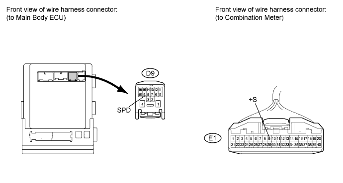
Disconnect the D9 ECU connector.
Measure the resistance according to the value(s) in the table below.
| Tester Connection | Condition | Specified Condition |
| D9-9 (SPD) - E1-9 (+S) | Always | Below 1 Ω |
|
| ||||
| OK | |
|
| 5.INSPECT COMBINATION METER ASSEMBLY |
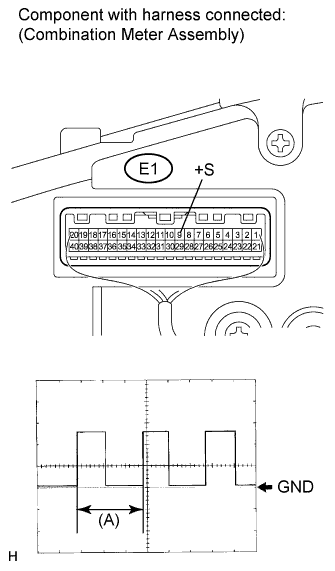 |
Check the output waveform.
Remove the combination meter with the connector(s) still connected (Click here).
Connect the oscilloscope to terminals E1-9 (+) and body ground.
Turn the engine switch on (IG).
Turn the wheel slowly.
Check the signal waveform according to the condition(s) in the table below.
| Item | Condition |
| Tool setting | 5 V/DIV., 20 ms./DIV |
| Vehicle condition | Driving at approx. 20 km/h |
|
| ||||
| OK | ||
| ||
| ||
| 6.CHECK HARNESS AND CONNECTOR (MAIN BODY ECU - JUNCTION CONNECTOR) |
Disconnect the D53 connector.
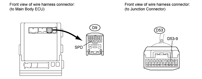
Measure the resistance according to the value(s) in the table below.
| Tester Connection | Condition | Specified Condition |
| D9-9 (SPD) - D53-9 | Always | Below 1 Ω |
|
| ||||
| OK | ||
| ||
| ||

