Home › COMMUNICATION SYSTEM › CAN COMMUNICATION › CAN COMMUNICATION SYSTEM

CAN COMMUNICATION SYSTEM > HOW TO PROCEED WITH TROUBLESHOOTING

for Preparation Click here


NOTICE:
  1. DTCs for the CAN communication system are as follows: U0073, U0100, U0123, U0124, U0126, U0129, U0230*2, U0327*1, U1002*1 *2 and B1499.
    *1: w/ Smart key system
    *2: w/ Power back door system
  2. Refer to troubleshooting of each system if DTCs regarding the CAN communication system are not output.


1.INSPECT BATTERY VOLTAGE

    Standard voltage:
    11 to 14 V

    HINT:
    If the voltage is below 11 V, recharge or replace the battery before proceeding.


NEXT


2.CHECK AND CLEAR DTCS

    HINT:
    1. CAN communication DTCs are output when there is an open or short in any of the communication wires. Any problems with the power source of a corresponding ECU or sensor, or problems in the ECU, the sensor itself also cause these DTCs to be output.
    2. If a CAN communication wire connector is disconnected with the ignition switch on (IG), the ECUs of the corresponding system and related systems record a DTC.


NEXT


3.CHECK INSTALLED SYSTEMS (ECU AND SENSOR) THAT USE CAN COMMUNICATION
  1. Based on the vehicle equipment and specifications, confirm the systems that use CAN communication (Click here).


NEXT


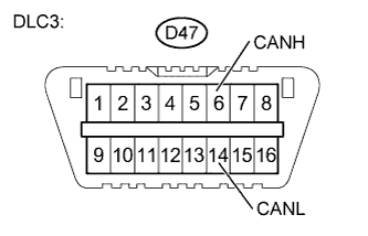
4.CHECK DLC3 BRANCH WIRE AND CAN NO. 1 BUS CIRCUIT MAIN WIRE (CANH - CANL)

    NOTICE:
    1. Turn the ignition switch off before measuring the resistances of the CAN main wire and the CAN branch wire.
    2. After the ignition switch is turned off, check that the key reminder warning system and light reminder warning system are not in operation.
    3. Before measuring the resistance, leave the vehicle as is for at least 1 minute and do not operate the ignition switch, any other switches or the doors. If the doors need to be opened in order to check the connectors, open the doors and leave them open.

    HINT:
    Operating the ignition switch, any other switches, or a door triggers related ECU and sensor communication on the CAN. This communication will cause the resistance value to change.

  1. Turn the ignition switch off.


  2. C118856E63
  3. Measure the resistance according to the value(s) in the table below.

    Standard resistance:
    Tester Connection
    Condition
    Result
    Proceed to
    D47-6 (CANH) - D47-14 (CANL)
    Ignition switch off
    54 to 69 Ω
    A
    D47-6 (CANH) - D47-14 (CANL)
    Ignition switch off
    70 Ω or higher
    B
    D47-6 (CANH) - D47-14 (CANL)
    Ignition switch off
    Below 54 Ω
    C


B.
GO TO CAN MAIN WIRE FOR DISCONNECTION (Click here)

C.
GO TO CHECK CAN BUS LINES FOR SHORT CIRCUIT (Click here)
A


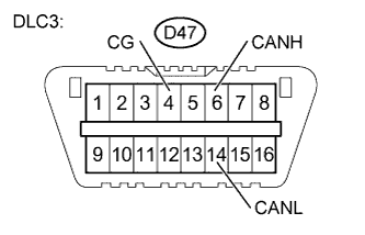
5.CHECK FOR SHORT TO GND IN CAN NO. 1 BUS (CANH, CANL - CG)
  1. Turn the ignition switch off.


  2. C118856E64
  3. Measure the resistance according to the value(s) in the table below.

    Standard resistance:
    Tester Connection
    Condition
    Specified Condition
    D47-6 (CANH) - D47-4 (CG)
    Ignition switch off
    200 Ω or higher
    D47-14 (CANL) - D47-4 (CG)
    Ignition switch off
    200 Ω or higher


NG.
GO TO CHECK CAN BUS LINE FOR SHORT TO GND (Click here)
OK


6.CHECK FOR SHORT TO +B IN CAN NO. 1 BUS (CANH, CANL - BAT)
  1. Disconnect the negative battery terminal.
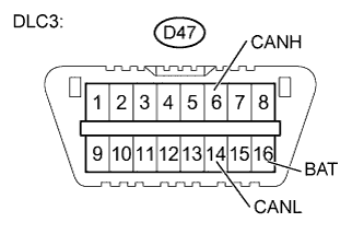


  2. C118856E65
  3. Measure the resistance according to the value(s) in the table below.

    Standard resistance:
    Tester Connection
    Condition
    Specified Condition
    D47-6 (CANH) - D47-16 (BAT)
    Disconnect negative battery terminal
    6 kΩ or higher
    D47-14 (CANL) - D47-16 (BAT)
    Disconnect negative battery terminal
    6 kΩ or higher


NG.
GO TO CHECK CAN BUS LINE FOR SHORT TO +B (Click here)
OK


7.CHECK TECHSTREAM
  1. Using Techstream, display the "Communication Bus Check" screen (Click here).

  2. Observe the screen for approximately 1 minute to check the ECUs and sensors displayed on the screen.

    Result:

    Result
    Proceed to
    All ECUs and sensors connected to the CAN communication system are displayed on the screen.
    (CAN bus circuit is currently normal)
    A
    One of the ECUs and sensors connected to the CAN communication system is not displayed on the screen.
    (Open in ECU or sensor branch wires, or communication interrupted)
    B(*1)
    Some ECUs and sensors repeatedly appear and disappear from the screen, during this check.
    (Open in one side of ECU or sensor branch wires)
    C
    1. All ECUs and sensors except the main body ECU connected to the CAN MS bus are not displayed on the screen.
    2. The main body ECU outputs DTC U1002.
    (Open in CAN MS bus main wire or short in CAN MS bus wire)
    D
    All ECUs and sensors connected to the CAN MS bus are not displayed on the screen.
    (Open in main body ECU branch wire or main body ECU malfunction)
    E

    NOTICE:
    1. The systems (ECUs, sensors) that adopt CAN communication vary depending on the vehicle and optional equipment. Check which systems (ECUs, sensors) are installed on the vehicle (Click here).
    2. Non-installed ECUs or sensors will not be displayed. Do not mistake them for being in the communication stop mode.
    3. The ECUs and sensors that repeatedly appear and disappear from the screen during this check are considered normal. (The response to Techstream and the tester display are affected by signals output from other ECUs which have an open circuit in either of their CAN branch wires.)

    HINT:
    1. (*1): See the "DTC CHART" instead of the "COMMUNICATION STOP MODE TABLE" when some of the ECUs connected to the CAN MS bus are not displayed on the screen (Click here).
    2. The ECUs connected to the CAN MS bus are displayed on the screen by the main body ECU.


B.
GO TO "COMMUNICATION STOP MODE TABLE" (Click here)

C.
GO TO "OPEN IN ONE SIDE OF CAN BRANCH WIRE" (Click here)

D.
GO TO "U1002 (CAN MS BUS)" (Click here)

E.
GO TO "MAIN BODY ECU COMMUNICATION STOP MODE" (Click here)
A


8.RECHECK DTC

    HINT:
    1. Sometimes CAN communication system DTCs are output, but all the ECUs and sensors connected to the CAN communication system are displayed on Techstream. In this case, previous or history DTCs may indicate the cause of the problem.
    2. ECUs related to a problem in the CAN bus will store DTCs to indicate communication malfunctions. The communication stop mode in the CAN bus can be determined by comparing the combination of DTCs that have been set. Refer to the DTC combination table for the CAN bus.
    3. The main body ECU will store communication error DTCs when the ECUs connected to the CAN MS bus cannot communicate, or if a network malfunction occurs.


    Result:

    Result
    Proceed to
    Communication error DTCs other than the codes output from the main body ECU is output. (A malfunction occurred in the CAN No. 1 bus)
    A
    The main body ECU outputs DTC U1002.
    (A malfunction occurred in the CAN MS bus)
    B
    The main body ECU outputs DTCs other than DTC U1002.
    (A malfunction occurred in an ECU branch wire connected to the CAN MS bus)
    C


B.
GO TO "U1002 (CAN MS BUS)" (Click here)

C.
GO TO "DTC CHART" (Click here)
A


9.DTC COMBINATION TABLE
  1. Confirm trouble according to the combination of output DTCs regarding the CAN communication system (Click here).

    HINT:
    Previous CAN communication system DTCs may be the cause if CAN communication system DTCs are output and all ECUs and sensors connected to the CAN communication system are displayed on Techstream's "Communication Bus Check" screen.


NEXT


10.CIRCUIT INSPECTION

    NEXT


    11.IDENTIFICATION OF PROBLEM

      NEXT


      12.REPAIR OR REPLACE

        NEXT


        13.CONFIRMATION TEST

          NEXT

          END