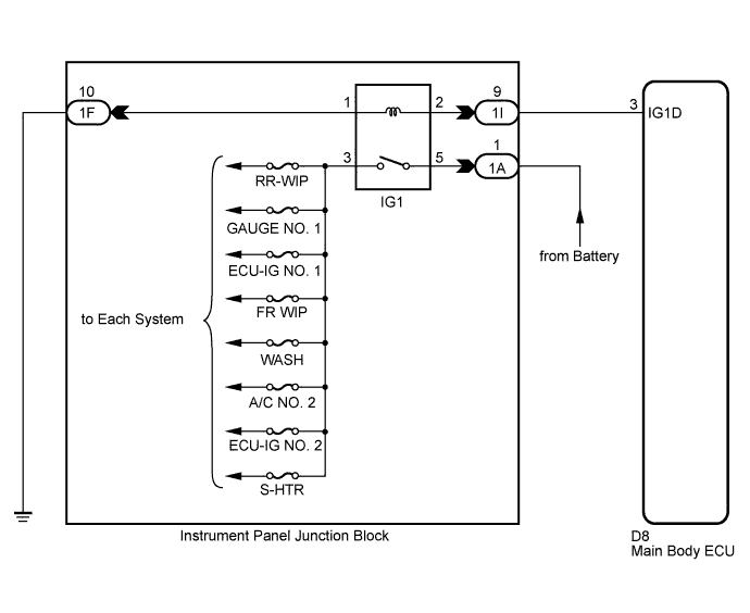
DTC B2272 Ignition 1 Monitor Malfunction |
| DTC No. | DTC Detection Condition | Trouble Area |
| B2272 | IG1 relay actuation circuit inside main body ECU (instrument panel junction block) or other related circuit is malfunctioning |
|
| 1.READ VALUE USING TECHSTREAM |
Connect Techstream to the DLC3.
Turn the engine switch on (IG) and turn Techstream main switch on.
Select the item below in the Data List, and read the display on the tester.
| Tester Display | Measurement Item/Range | Normal Condition | Diagnostic Note |
| IG1 Relay Mon1 | Status of IG1 relay monitor (outer) / ON or OFF | ON: Engine switch on (IG) (IG1 relay is ON) OFF: Engine switch off (IG1 relay is OFF) | - |
|
| ||||
| OK | |
 |
| 2.CHECK ENGINE SWITCH CONDITION |
Check the power source mode change.
When the key is inside the vehicle and the shift lever is in the P position, check that pressing the engine switch causes the power source mode to change as follows:
|
| ||||
| OK | |
|
| 3.CHECK DTC OUTPUT |
Delete the DTCs (Click here).
Check for DTCs again.
|
| ||||
| OK | ||
 | ||
| ||
| 4.INSPECT RELAY (IG1 RELAY) |
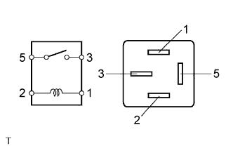 |
Remove the IG1 relay from the instrument panel junction block.
Measure the resistance according to the value(s) in the table below.
| Tester Connection | Condition | Specified Condition |
| 3 - 5 | When battery voltage is not applied to terminals 1 and 2 | 10 kΩ or higher |
| 3 - 5 | When battery voltage is applied to terminals 1 and 2 | Below 1 Ω |
|
| ||||
| OK | |
|
| 5.CHECK HARNESS AND CONNECTOR (INSTRUMENT PANEL JUNCTION BLOCK - MAIN BODY ECU) |
Disconnect the 1I junction block connector.
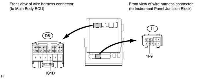
Disconnect the D8 ECU connector.
Measure the resistance according to the value(s) in the table below.
| Tester Connection | Condition | Specified Condition |
| 1I-9 - D8-3 (IG1D) | Always | Below 1 Ω |
| D8-3 (IG1D) - Body ground | Always | 10 kΩ or higher |
|
| ||||
| OK | |
|
| 6.CHECK HARNESS AND CONNECTOR (INSTRUMENT PANEL JUNCTION BLOCK - BATTERY AND BODY GROUND) |
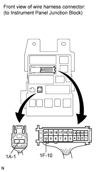 |
Disconnect the 1F and 1A junction block connectors.
Measure the resistance according to the value(s) in the table below.
| Tester Connection | Condition | Specified Condition |
| 1F-10 - Body ground | Always | Below 1 Ω |
Measure the voltage according to the value(s) in the table below.
| Tester Connection | Condition | Specified Condition |
| 1A-1 - Body ground | Always | 11 to 14 V |
|
| ||||
| OK | ||
| ||
| ||

