Home › BRAKE › BRAKE CONTROL › YAW RATE AND ACCELERATION SENSOR

YAW RATE AND ACCELERATION SENSOR > INSTALLATION

for Preparation Click here


1. INSTALL YAW RATE AND ACCELERATION SENSOR


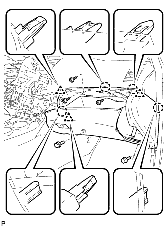
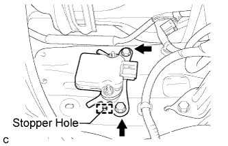
    C165812E01
  1. Install the yaw rate and acceleration sensor with the 2 bolts.

    Torque:
    15 N*m{ 153 kgf*cm , 11 ft.*lbf }

    NOTICE:
    1. Be sure to insert the yaw rate and acceleration sensor claw into the stopper hole while installing the yaw rate and acceleration sensor.
    2. Do not damage the yaw rate and acceleration sensor.
    3. Make sure that the yaw rate and acceleration sensor is installed securely.
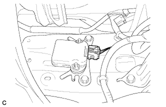


    C165813
  1. Connect the connector to the yaw rate and acceleration sensor.

    NOTICE:
    Make sure that the yaw rate and acceleration sensor connector is connected securely.


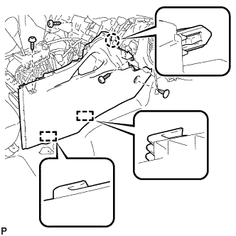
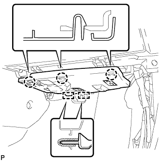
2. INSTALL FRONT NO. 2 CONSOLE BOX INSERT


    B168374
  1. Engage the claw and 2 guides.

  1. Install the front No. 2 console box insert with the 3 screws <F> and clip.


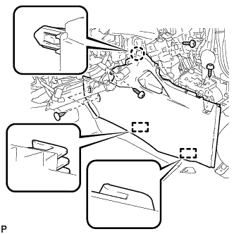
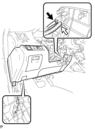
3. INSTALL FRONT NO. 1 CONSOLE BOX INSERT


    B168373
  1. Engage the claw and 2 guides.

  1. Install the front No. 1 console box insert with the 3 screws <F> and 2 clips.


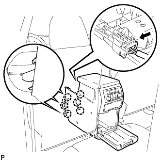
4. INSTALL CONSOLE BOX ASSEMBLY (w/ Rear Air Conditioning System)


    B175149
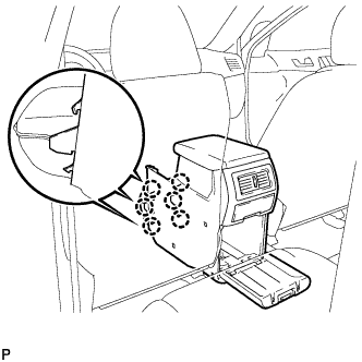
  1. Engage the 6 claws.

  1. Connect the connector.


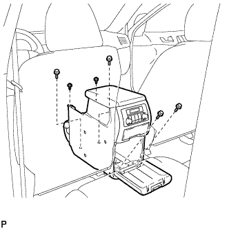
    B181135
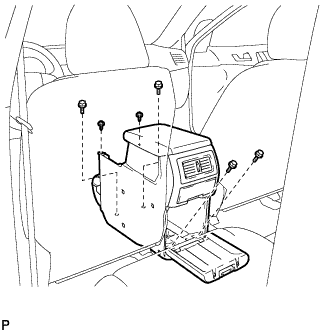
  1. Install the console box assembly with the 4 bolts and 2 screws.


5. INSTALL CONSOLE BOX ASSEMBLY (w/o Rear Air Conditioning System)


    B173629
  1. Engage the 6 claws.


    B173628
  1. Install the console box assembly with the 4 bolts and 2 screws.


6. INSTALL LOWER REAR CONSOLE BOX
  1. Install the lower rear console box.


7. INSTALL NO. 2 CONSOLE BOX DUCT (w/o Rear Air Conditioning System)


    B173013
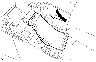
  1. Install the No. 2 console box duct as shown in the illustration.


8. INSTALL UPPER CONSOLE PANEL SUB-ASSEMBLY


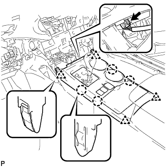
    B168372
  1. Connect the connector.

  1. Engage the 4 claws and 4 clips, and install the upper console panel sub-assembly.


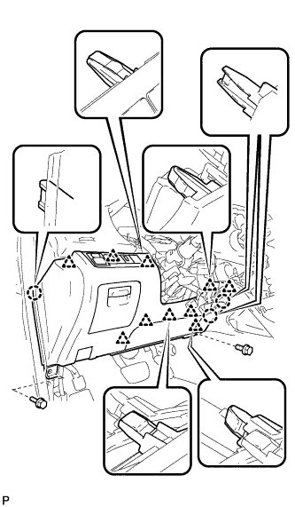
9. INSTALL LOWER INSTRUMENT PANEL SUB-ASSEMBLY
  1. Connect each connector and clamp.


    B168370
  1. Engage the 4 claws and 3 clips.

  1. Install the lower instrument panel sub-assembly with the 2 bolts <B> and 3 screws <F>.


10. INSTALL NO. 2 INSTRUMENT PANEL UNDER COVER SUB-ASSEMBLY


    B173000
  1. Engage the 2 guides.

  1. Engage the 3 claws and install the No. 2 instrument panel under cover sub-assembly.


11. INSTALL COWL SIDE TRIM SUB-ASSEMBLY RH

HINT:
Use the same procedure for the RH side and the LH side.


12. INSTALL FRONT DOOR SCUFF PLATE RH

HINT:
Use the same procedure for the RH side and the LH side.


13. INSTALL LOWER INSTRUMENT PANEL FINISH PANEL SUB-ASSEMBLY (for Automatic Air Conditioning System)


    B173009
  1. Connect the hood lock control cable assembly.

  1. Connect each connector and the aspirator duct.


    B173021
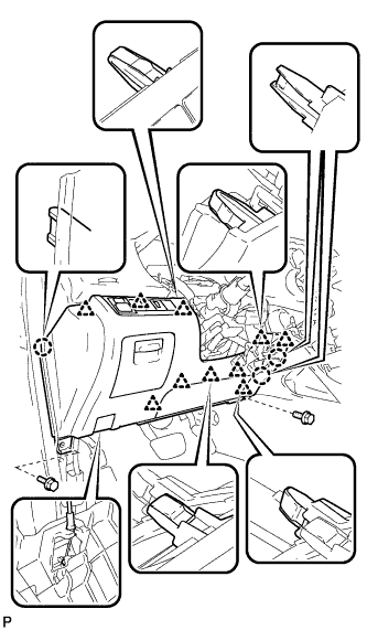
  1. Engage the 3 claws and 10 clips.

  1. Install the lower instrument panel finish panel sub-assembly with the 2 bolts <B>.


14. INSTALL LOWER INSTRUMENT PANEL FINISH PANEL SUB-ASSEMBLY (for Manual Air Conditioning System)


    B168371
  1. Connect the hood lock control cable assembly.

  1. Connect each connector.

  1. Engage the 3 claws and 10 clips.

  1. Install the lower instrument panel finish panel sub-assembly with the 2 bolts <B>.


15. REMOVE COWL SIDE TRIM SUB-ASSEMBLY LH


    B173227
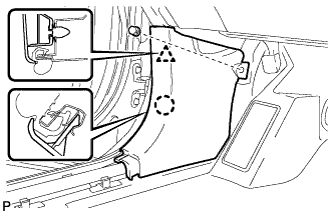
  1. Engage the claw and clip, install the cowl side trim sub-assembly LH.

  1. Install the clip.


16. REMOVE FRONT DOOR SCUFF PLATE LH


    B173224
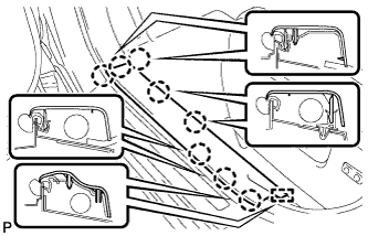
  1. Engage the guide and the 8 claws, and install the front door scuff plate LH.


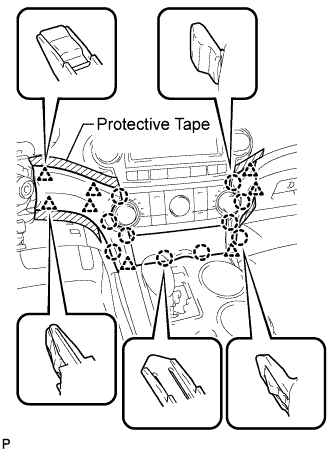
17. INSTALL CENTER INSTRUMENT CLUSTER FINISH PANEL ASSEMBLY (w/ Smart Key System)


    B184681E01
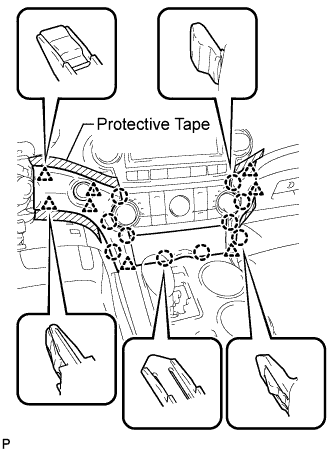
  1. Apply protective tape to the areas shown in the illustration.

  1. Connect each connector.

  1. Engage the 10 claws and 8 clips, and install the center instrument cluster finish panel assembly.

    NOTICE:
    Do not the damage the instrument panel safety pad assembly and lower instrument panel finish panel sub-assembly.


18. INSTALL CENTER INSTRUMENT CLUSTER FINISH PANEL ASSEMBLY (w/o Smart Key System)


    B184679E01
  1. Apply protective tape to the areas shown in the illustration.

  1. Connect each connector.

  1. Engage the 10 claws and 8 clips, and install the center instrument cluster finish panel assembly.

    NOTICE:
    Do not the damage the instrument panel safety pad assembly and lower instrument panel finish panel sub-assembly.


19. CONNECT CABLE TO NEGATIVE BATTERY TERMINAL

NOTICE:
When disconnecting the cable, some systems need to be initialized after the cable is reconnected. (Click here)


20. PERFORM YAW RATE AND ACCELERATION SENSOR ZERO POINT CALIBRATION
(Click here)


21. CHECK FOR YAW RATE SENSOR SIGNAL
(Click here)