Home › HYBRID SYSTEM ยท Q211 HYBRID TRANSMISSION / TRANSAXLE › REAR TRACTION MOTOR

REAR TRACTION MOTOR > INSTALLATION

for Preparation Click here


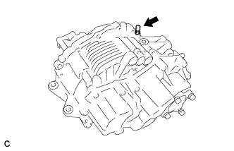
1. INSTALL BREATHER PLUG


    C173271
  1. Install the breather plug.

    Torque:
    21 N*m{ 214 kgf*cm , 15 ft.*lbf }


2. INSTALL EXTENSION WIRE ASSEMBLY


    C105724
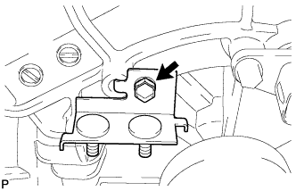
  1. Install the wire harness clamp bracket to the rear traction with transaxle motor with the bolt.
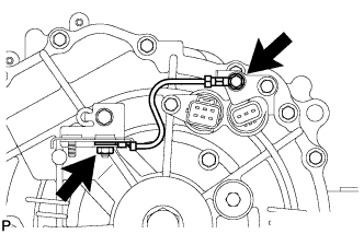
    Torque:
    5.5 N*m{ 56 kgf*cm , 49 in.*lbf }


    C105723
  1. Install the wire harness clamp bracket and ground wire to the rear traction with transaxle motor with the bolt and nut.
    Torque:
    5.5 N*m{ 56 kgf*cm , 49 in.*lbf }


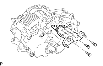
    C105721
  1. Install the extension wire to the rear traction with transaxle motor with the 3 bolts.

    Torque:
    10 N*m{ 102 kgf*cm , 7 ft.*lbf }

    CAUTION:
    Be sure to securely insert the extension wire assembly into the rear traction motor.


3. INSTALL FRONT DIFFERENTIAL SUPPORT ASSEMBLY


    C178474
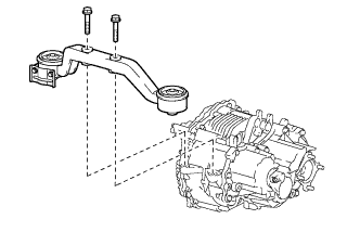
  1. Install the front differential support assembly to the rear traction with transaxle motor with new 2 bolts.

    Torque:
    80 N*m{ 815 kgf*cm , 59 ft.*lbf }


4. INSTALL REAR TRACTION WITH TRANSAXLE MOTOR ASSEMBLY


    C178488E02
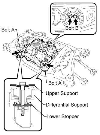
  1. Temporarily install the rear traction motor (front side) with the 2 lower stoppers, 2 upper supports, and 2 new bolts (A) as shown in the illustration.

  1. Temporarily install the rear traction motor (rear side) with the 2 new bolts (B).

  1. Fully tighten the 2 bolts (A).

    Torque:
    103 N*m{ 1050 kgf*cm , 76 ft.*lbf }

  1. Fully tighten the 2 bolts (B).

    Torque:
    95 N*m{ 970 kgf*cm , 70 ft.*lbf }


5. TEMPORARILY INSTALL REAR SUSPENSION MEMBER SUB-ASSEMBLY


    C171845
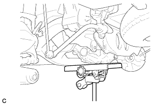
  1. Raise the rear suspension member with a jack.

    HINT:
    Support the rear suspension member until retightening of the suspension member is complete.


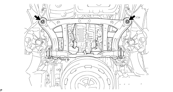
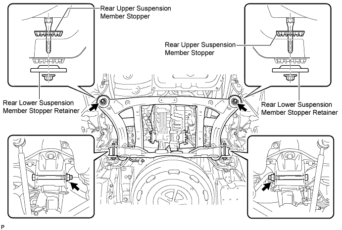
  1. Temporarily install the rear suspension member, the 2 rear upper suspension member stoppers and rear lower suspension member stopper retainers with the 4 nuts and the 2 bolts.

    C171850E01


  1. Fully tighten the 2 nuts.


    C171851

    Torque:
    115 N*m{ 1170 kgf*cm , 85 ft.*lbf }


6. FULLY TIGHTEN REAR SUSPENSION MEMBER SUB-ASSEMBLY


    C167779E01
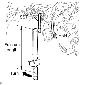
  1. Using SST and a socket wrench (19 mm), fully tighten the nut (LH side).
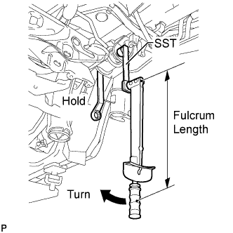
    Torque:
    without SST:
    181 N*m{ 1850 kgf*cm , 133 ft.*lbf }
    with SST:
    134 N*m{ 1366 kgf*cm , 98 ft.*lbf }

    SST
    09961-00950  

    NOTICE:
    1. Use a torque wrench with a fulcrum length of 425 mm (16.73 in.).
    2. This torque value is effective when SST is parallel to the torque wrench.


    C166256E01
  1. Using SST and a socket wrench (19 mm), fully tighten the nut (RH side).

    Torque:
    without SST:
    181 N*m{ 1850 kgf*cm , 133 ft.*lbf }
    with SST:
    134 N*m{ 1366 kgf*cm , 98 ft.*lbf }

    SST
    09961-00950  

    NOTICE:
    1. Use a torque wrench with a fulcrum length of 425 mm (16.73 in.).
    2. This torque value is effective when SST is parallel to the torque wrench.


7. CONNECT NO. 3 WIRE FRAME


    C105715
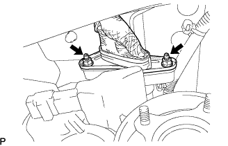
  1. Wear insulated gloves. Install the No. 3 frame wire to the rear traction motor with the 2 nuts.
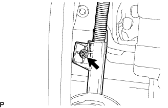
    Torque:
    15 N*m{ 153 kgf*cm , 11 ft.*lbf }


    C105714
  1. Install the wire harness clamp to the vehicle with the nut.
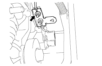
    Torque:
    8.5 N*m{ 87 kgf*cm , 75 in.*lbf }


    C170295
  1. Install the ground cable to the rear traction motor with the nut.
    Torque:
    5.5 N*m{ 56 kgf*cm , 49 in.*lbf }


    C105713
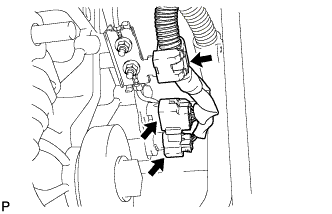
  1. Connect the 2 connectors and clamp to the rear traction motor.


8. CONNECT NO. 3 PARKING BRAKE CABLE ASSEMBLY


    C105712
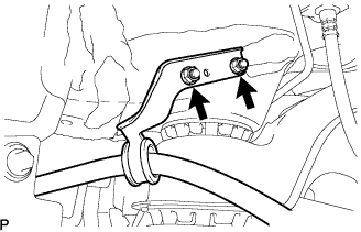
  1. Install the No. 3 parking brake cable assembly with the 2 nuts.

    Torque:
    6.0 N*m{ 61 kgf*cm , 53 in.*lbf }


9. CONNECT NO. 2 PARKING BRAKE CABLE ASSEMBLY

HINT:
Install the RH side by following the same procedures as for the LH side.


10. INSTALL REAR DRIVE SHAFT ASSEMBLY LH
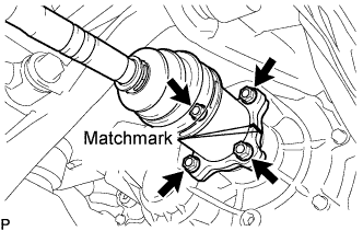
  1. Align the matchmarks.


    C108295E02
  1. Install the rear drive shaft assembly with the 4 nuts and washers.

    Torque:
    56 N*m{ 571 kgf*cm , 41 ft.*lbf }


11. INSTALL REAR DRIVE SHAFT ASSEMBLY RH

HINT:
Install the RH side by following the same procedures as for the LH side.


12. TEMPORARILY TIGHTEN REAR NO. 2 SUSPENSION ARM ASSEMBLY LH


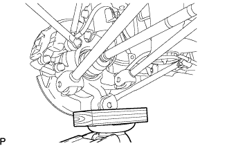
    C105711
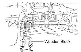
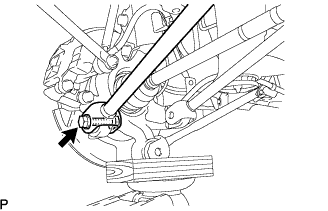
  1. Jack up the rear axle carrier, placing a wooden block to avoid damage.


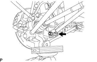
    C105710
  1. Temporarily tighten the rear No. 2 suspension arm assembly LH with the bolt and nut.

    HINT:
    Insert the bolt from the rear side of the vehicle and lightly tighten the bolt.


13. TEMPORARILY TIGHTEN REAR NO. 2 SUSPENSION ARM ASSEMBLY RH

HINT:
Install the RH side by following the same procedures as for the LH side.


14. TEMPORARILY TIGHTEN REAR NO. 1 SUSPENSION ARM ASSEMBLY LH


    C105709
  1. Temporarily tighten the rear No. 1 suspension arm assembly LH with the bolt and nut.

    HINT:
    Insert the bolt from the front side of the vehicle and lightly tighten the bolt.


15. TEMPORARILY TIGHTEN REAR NO. 1 SUSPENSION ARM ASSEMBLY RH

HINT:
Install the RH side by following the same procedures as for the LH side.


16. TEMPORARILY TIGHTEN REAR STRUT ROD ASSEMBLY


    C105708
  1. Temporarily tighten the rear strut rod assembly with the bolt and nut.

    HINT:
    Insert the bolt from the inside of the vehicle and lightly tighten the bolt.


17. STABILIZE SUSPENSION


    C166003E01
  1. Jack up the rear axle carrier sub-assembly, placing a wooden block underneath to avoid damage. Apply load to the suspension so that the rear drive shaft assembly is positioned horizontally.

    CAUTION:
    Do not jack up the rear axle carrier sub-assembly too high as the vehicle may fall.

    NOTICE:
    Do not bend the brake dust cover.

    HINT:
    1. If the rear drive shaft assembly cannot be positioned horizontally as shown in the illustration even when the rear axle carrier sub-assembly is jacked up, apply additional load to the vehicle such as by having a person sit in the rear seat.
    2. Use the same procedure for the RH side and LH side.


18. FULLY TIGHTEN REAR NO. 2 SUSPENSION ARM ASSEMBLY LH


    C105710
  1. Fully tighten the bolt.

    Torque:
    112 N*m{ 1141 kgf*cm , 82 ft.*lbf }

    NOTICE:
    Turn the bolt while holding the nut.


19. FULLY TIGHTEN REAR NO. 2 SUSPENSION ARM ASSEMBLY RH

HINT:
Install the RH side by following the same procedures as for the LH side.


20. FULLY TIGHTEN REAR NO. 1 SUSPENSION ARM ASSEMBLY LH


    C105709
  1. Fully tighten the bolt.

    Torque:
    112 N*m{ 1141 kgf*cm , 82 ft.*lbf }


21. FULLY TIGHTEN REAR NO. 1 SUSPENSION ARM ASSEMBLY RH

HINT:
Install the RH side by following the same procedures as for the LH side.


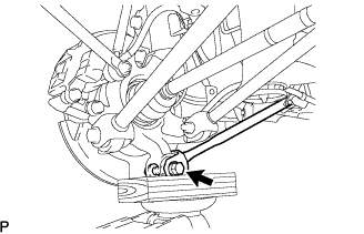
22. FULLY TIGHTEN REAR STRUT ROD ASSEMBLY


    C105708
  1. Fully tighten the bolt.

    Torque:
    80 N*m{ 815 kgf*cm , 59 ft.*lbf }

    NOTICE:
    Turn the bolt while holding the nut.


23. INSTALL REAR AXLE SHAFT LH NUT
  1. Clean the threaded parts on the drive shaft and axle hub nut using a non-residue solvent.
    NOTICE:
    1. Be sure to perform this work for a new drive shaft.
    2. Keep the threaded parts free of oil and foreign objects.


    C165541
  1. Install a new rear axle shaft nut.

    Torque:
    294 N*m{ 2996 kgf*cm , 216 ft.*lbf }

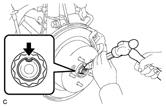
  1. Using a chisel and hammer, stake the rear axle shaft nut.


24. INSTALL REAR AXLE SHAFT RH NUT

HINT:
Install the RH side by following the same procedures as for the LH side.


25. INSPECT AND ADJUST REAR WHEEL ALIGNMENT
(Click here)


26. INSTALL EXHAUST PIPE ASSEMBLY
(Click here)


27. INSTALL REAR WHEELS

Torque:
103 N*m{ 1050 kgf*cm , 76 ft.*lbf }


28. CONNECT CABLE TO NEGATIVE BATTERY TERMINAL

NOTICE:
When disconnecting the cable, some systems need to be initialized after the cable is reconnected (Click here).


29. ADD AND INSPECT HYBRID TRANSAXLE FLUID
  1. Add transaxle fluid.


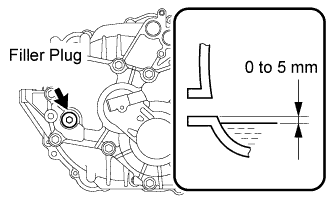
    C170291E02
  1. Check that the fluid surface is within 5 mm (0.20 in.) from the lowest position of the inner surface of the transaxle filler plug opening.

    NOTICE:
    1. Stop the vehicle on a flat road.
    2. Recheck the transaxle fluid level after driving when exchanging oil.
    3. Insufficient or excessive amounts of transaxle fluid may be the cause of some trouble.

  1. Check for leaks if the transaxle fluid level is low.

  1. Using a socket hexagon wrench 10 mm, install the filler plug and a new gasket.

    Torque:
    39 N*m{ 398 kgf*cm , 29 ft.*lbf }


30. CHECK HIGH VOLTAGE CABLE CONNECTION

NOTICE:
Be sure to wear insulated gloves and protective goggles.


    C105715
  1. Make sure that the No. 3 frame wire is securely installed with the nuts.

    NOTICE:
    1. Do not install the No. 3 frame wire at an angle.
    2. Be sure to tighten the nuts securely.


31. INSTALL SERVICE PLUG GRIP

NOTICE:
Before connecting the service plug, check that no parts and tools remain and that the high voltage terminals and connectors are connected securely.


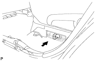
    A176049
  1. Wear insulated gloves, then insert the service plug.

  1. Push down on the grip to lock.


    A175635
  1. Close the reclining hinge cover.

    NOTICE:
    Check that the 2 clips are securely connected to the battery carrier bracket (click sound).


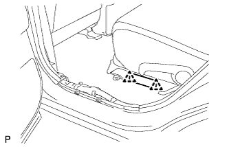
    A175634
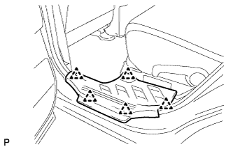
  1. Close the rear door scuff plate LH.

    NOTICE:
    Check that the 5 clips are securely connected to the battery carrier bracket (click sound).


32. INSPECT FOR EXHAUST GAS LEAK